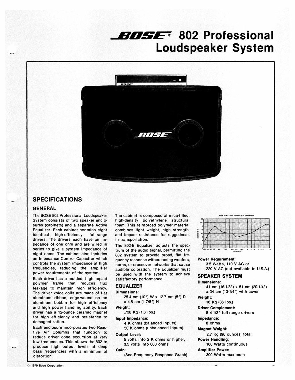
Bose 802 i speaker eq manual
This is the 5 pages manual for bose 802 i speaker eq manual.
Read or download the pdf for free. If you want to contribute, please upload pdfs to audioservicemanuals.wetransfer.com.
Extracted text from bose 802 i speaker eq manual (Ocr-read)
Page 1
Figure 1 SPEAKER SCHEMATICFigure 2 DRIVER PLACEMENT (FRONT VIEW) I. DISASSEMBLY PROCEDURE 1. GRILLE":'" Remove the twoclinch nuts andgrille retainer holdingthegrille in place. Lift thegrille bypulling from the hole in the grille's center. Carefully remove the grilleand place in a safe locationuntilneeded for reassembly. 2. BACK PANEL - Remove driverstwo (2) and three (3) to obtainaccess to the internalrear panel connections. This will provide access for repairs associated with theinternalconnections of the back panel. 3. IMPEDANCE CONTROL NETWORK - Remove driverstwo (2) and three (3) to obtainaccess to theimpedance controlassembly. This will allow acontinuity checkof the bulb circuit and a check of the wiringandimpedance controlcapacitor. II. TEST PROCEDURE 1. CONTINUITY CHECK - An open drivermay be detected by using an ohmmeterandchecking continuity. Inserta phone jack in the rear of the speaker and checkcontinuity bycarefully penetrating the blackcementcovering theflexible conductor on thesurface of each cone with an ohmmeter lead. Check continuitybetween each driverand the speaker terminalsuntilthe open driverisdetected. See Figures 1 and 2. 2. POWER CHECK - Using a 50-watt (20 volt) sine wave signal, sweep the range between 40 and 200 Hz. Check for rattles,buzzing or voice coilrubbing. Reduce the output to 5 watts (6.5 volts), and continueto sweep the range between 200 and 16,000 Hz. Note: When us ing a sine wave signal on the 802 Speaker System, do not operatethe speaker below 80 Hz at levels greater than 20 watts(12.6 volts) as possible damage to the driversmay occur. 3. PHASING CHECK - Using a 6- to 20-volt batteryor DC power supply,checkthat all speakers are in phase (moving together).Connect the positive portionof the power supplyto the "tip" terminal of the phone jack and the groundconnection of the power supplyto the "sleeve" terminalof the phone jack. This will produceanoutward motionof all drivers. See Figure 1. 4. IMPEDANCE CONTROL NETWORK - Check the bulb circuitryandwiring of theimpedance controlcircuitry by using an 8 kHz sine wave signal at 2V RMS ±1%. Insert a 0.5 ohm ±1% resistor in series with the groundlead for the speaker. A voltagedrop of 60-77 mV RMS shouldbe measured across theresistor. Ifincorrect, checkthe bulb(s) and capacitor. III. SERVICE NOTES 1. Whenreplacing 802 drivers, be certainto use the 802 drivergasket (Part number110943) to properlyseal thedriverto the 802 cabinet. 2. Check the couplingcontrolinsertsfordirt or dust. If they are clogged,replace them with the spares provided in the top cover of the 802 speaker. Extra couplingcontrolinsertsmay be obtained throughthe BOSE CustomerServiceDepartment or your BOSE Professional Products Dealer. One of the unusualfeatures of the 802 is the use of the couplingcontrolinserts. These are polyester "fuzz" discs which are installedin the Reactive Air Columns. Theirpurpose is todecouple thedrivers from one anothernear the resonant frequency of the system. After prolonged use, these insertsandtheir gauze covers may become plugged withdirtor dust, causingthem to lose theireffec tiveness. Thisresults in a "buzzing" soundduring heavy bass passages. The inserts may be easily removed for inspectionorreplacement (two spare sets of insertsaresupplied with the 802): (See Figure 3): a. Remove the two clinchnutsbyrotating themcounter-clockwise. b. Remove the grilleretainer and the grille. c. Remove the two columnextenders bypinching both release tabs and pullinggently. Do not use sharp toolsas they could damage the thin seal lip. d. Remove the snap caps from the columnextenders by prying them off gentlywith your fingernails. e. Examine the couplingcontrolinsertsfor dirt ordust. If they are clogged,replace them withthe spares provided. f. Wash the gauze-covered ends of the columnextenders byswishing them around in warm, soapy water. Rinse in clear water and allow them to air-dry thoroughly. g. Reassemble the system by reversing the above procedure, pushingthecolumn extenders infirmly untilthey snap intoplace. Be certain tocenter thegrille retainer beforetightening theclinch nuts.Tighten theclinch nuts firmly but not excessively. h. Extra coupling controlinsertsmay be obtained throughthe BOSE CustomerServiceDepartment or your BOSE ProfessionalPro ducts Dealer. This is the only periodicmaintenance requiredby the 802 system.
Page 2
CLINCH NUTS -- _ GRILLERETAINER _------Il~ GRILLE PANEL _------1111.2: COLUMN EXTENDERS COUPLING CONTROL INSERTS-________ I ~ ---- ..........:::=:~ .. --=-.-.,......:=-: SNAP CAPS