Beomaster4500
This is the 5 pages manual for beomaster4500.
Read or download the pdf for free. If you want to contribute, please upload pdfs to audioservicemanuals.wetransfer.com.
Extracted text from beomaster4500 (Ocr-read)
Page 1
Beomaster 4500 setting-up guide
Contents
3 Where to put the Beomaster
4 Connections
7 Headphones
8 Audio/video system setup
For the US market only:
am ov men- men: I
new on- e
CAUTION: To reduce the risk
ol electric shock, do not
remove cover (or back).
No user-serviceable ports
inside. Rater servicing to
qualified service personnel.
WARNING: To prevent fire or
electric shock, do not expose
this appliance to rain or
moisture.
This symbol indicates that a
dangerous voltage constitut-
ing a risk at electric shock is
present within this unit.
This symbol indicates that
there are important operat-
ing and maintenance instruc-
tions In the literature accom-
panying this unit.
9%
See the Beosystem 4500 users guide (also
enclosed) for detailed operating instructions.
Where to put the Beomaster
The Beomaster 4500 must be placed so
that ventilation is not impeded. Avoid
placing it in direct sunlight, near
radiators or other sources of heat
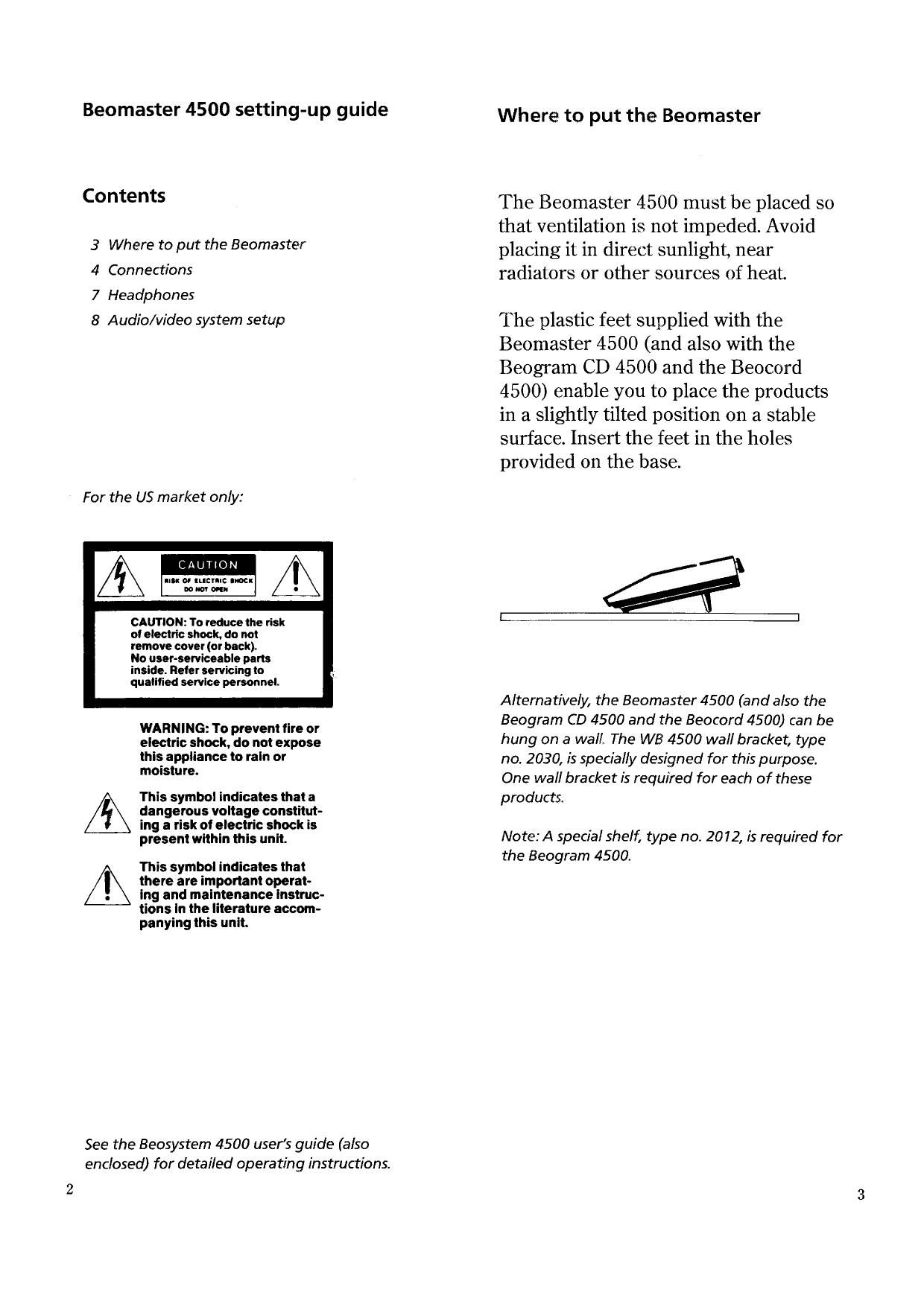
The plastic feet supplied with the
Beomaster 4500 (and also with the
Beogram CD 4500 and the Beocord
4500) enable you to place the products
in a slightly tilted position on a stable
surface. Insert the feet in the holes
provided on the base.
Alternatively, the Beomaster 4500 (and also the
Beogram CD 4500 and the Beocord 4500) can be
hung on a wall, The WB 4500 wall bracket, type
no. 2030, is specially designed for this purpose.
One wall bracket is required for each of these
products.
Note: A special shelf, type no. 2012, is required for
the Beogram 4500.
Page 2
Connections
Connect loudspeakers, antennae and the
other units in the Beosystem (if any) to
the Beomaster before connecting it to the
mains.
Once connected to the mains, the
Beomaster is in stand-by mode and
ready to be operated. The Beomaster is
designed to be left in stand-by mode
when not in use.
AM Beogram 4500
antenna ( or a second
tape recorder
or CD player)
The metal bar supplied with the Beomaster 4500
is for concealing cables. When you have made the
necessary connections, insert the bar in the holes
provided on the rear panel and press downwards.
Active Active Passive
speakers speakers speakers
(Power (Power (8 ohms)
Link) Link)
Right Left
FM
Antenna
Beogram
CD 4500
Local
Compatible
Bang & Olufsen TV Control
(or other auxiliary System
Beocord
4500 equipment) (MCL)
Page 3
> Connections
Connection options
The sockets PH/TPZ and AUX/TV can
be programmed to accommodate
different types of equipment If for
example you want to connect a second
tape recorder to the AUX/TV socket,
you simply change the option of the
Beomaster.
When the Beomaster 4500 leaves the
factory, it is set to the PHONO option.
The connections shown on the previous
page apply to this option.
If the Beomaster is set to the CD option,
a second Bang & Olufsen tape recorder
can be connected to the AUX/TV
socket, instead of a Bang & Olufsen TV.
If the Beomaster is set to the TAPE 2
option, a second Bang & Olufsen tape
recorder can be connected to the PH/
T P2 socket, instead of the Beogram
4500.
To set the Beomaster to the option of your
choice, you must first switch it to the stand-by
mode.
Then press PROGRAMMING and 7 simultaneously.
The current option is now displayed: PHONO OP,
CD OP, or TAPE 2 OP.
While the option is displayed, press PHONO, CD, or
TAPE 2 as appropriate to select your option.
Headphones
The tiny socket on the front of the
Beomaster is for headphones, e.g. the
Bang & Olufsen Form 1 or Form 2
headphones.
Note: If you plug in headphones, the loudspeakers
are cut out (except any loudspeakers connected
to the sockets marked R/L 2).