Audio technica 705 owners manual

This is the 4 pages manual for audio technica 705 owners manual.
Read or download the pdf for free. If you want to contribute, please upload pdfs to audioservicemanuals.wetransfer.com.

Page: 1 / 4
audio technica 705 owners manual

Extracted text from audio technica 705 owners manual (Ocr-read)


Page 1

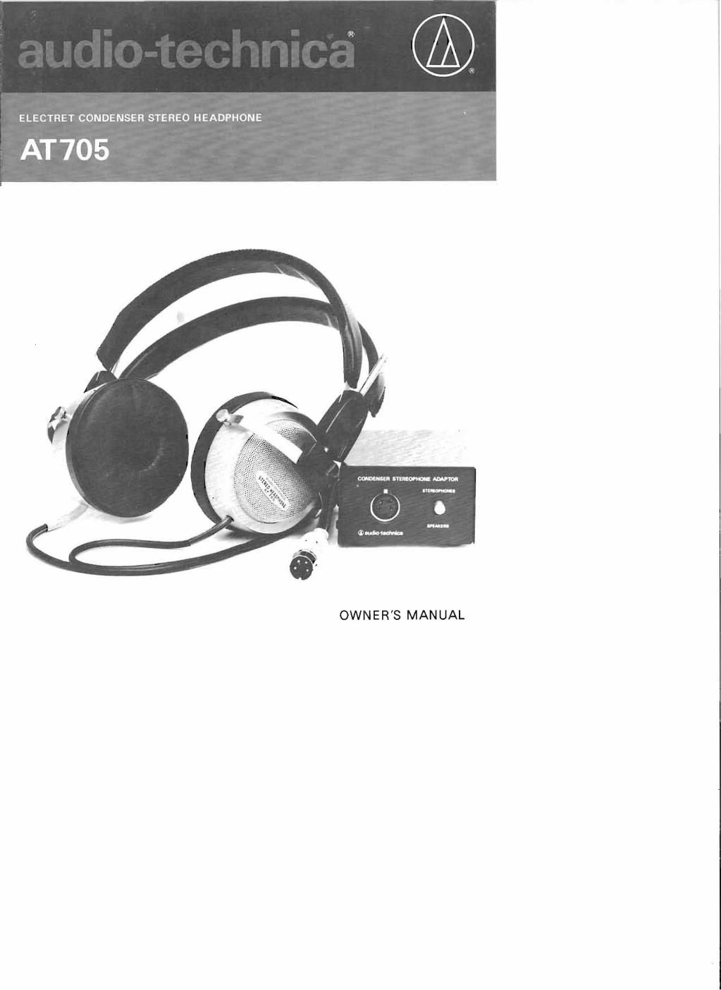
Your new AT705 stereo headphone consists of a lightweight, comfortable headphone and a separate impedance matching adapter which connects to the amplifier output of your stereo system. The technical expertise and manufacturing skill of Audio­ Technica, makers of the highly acclaimed Dual Magnet phono cartridges, were fully exploited to bring you this excellent head­ phone set featuring a wide-range flat response and clear, nat­ ural sound. As with our other headphone models, the functionally sen­ sible bi-polar, open-back construction was applied to this head­ phone. This design not only reduces weight and bulk but also improves transient response and eliminates the "closed- in" feel­ ing which is a cause of discomfort when using the convention ­ ai , closed- back headphone. The convenient impedance matching adapter does not re­ quire a separate power source, thus eliminating the usual cause of static and possible damage to the driver units. Simply hook it up to your stereo amplifier and you are ready for an expe­ rience in superb music enjoyment. YOUR AMPLIFIER The adapter can be connected to any ampli­ fier with an output of over 3 watts and de­ signed for use with 4 to 16-ohm speakers, either transistor or tube type , or even a pro­ fessional BTL model. Since the AT705 is a CONNECTIONS highly sensitive instrument , your amplifier should be of a comparable high quality with low distortion and noise levels. The adapter should be connected to the speaker terminals of the amplifier, not the headphone terminals. The connecting cords of the adapter are color­ coded as follows: Red : R +(right channel) Black: R - (right ground) White: L +(left channel) Blue: L - (left ground) 1. After switching off the power supply of your amplifier, remove the speaker cords from the terminals and connect the adapter cords as illustrated below(Fig . 1) . In some ampli­ fier models the channel terminals may be marked "8 ohms " and the ground terminals as "0" or " Common." In the case of a tube model where the plus terminals are separated into 4-ohm, 8-ohm and 16-ohm, test-listen using each terminal and select the best one. Generally speaking, the finest effect is ob­ tained through the 16-ohm terminal. AMPLIFIER SPEAKER TERMINALS + Fig.1

Page 2

".~...,1"'" -4- ..... . AEDfWHJTE IlL 1':-- : .~ . .~ , i:t~~~' - 0 ',' II , AMPUFlER ~__ 7-----*_-' ~~~~E ~S BLAC lC/ BlUE...,--­ I - Ii - I'li i - ~ . . - Fig . 2 ADAPTER CIRCUIT DIAGRAM Fig.3 FREOUENCY RESPONSE CURVE (B&K) OPERATION 1. First, be sure that the amplifier volume is squelched to min· ~,~- .. imum level since a . ....­ sudden input of ex· cessive power can iiI_' :"- _.... U - damage the driver units of the headphone . 2. Adjust the headphone so that the earpads rest snugly over your ears. Space between the EARPADS pads and your ears will cause adverse effects at low frequency response. 3. When the adapter switch is flipped to " Stereophones" position the circuit to the headphone will be completed. Switch on the amplifier and gradually raise the volume to the optimum level. Switching from phones to speakers or vice versa should always be done with the amplifier volume at minimum level. The earpads used on the AT705 are designed and con· structed to comple· ment the fine per· formance of the equipment. They can be detached for cleaning by firmly holding the frame and slightly turning clock· ADDITIONAL NOTES