Audio technica 231 lp brochure
This is the 2 pages manual for audio technica 231 lp brochure.
Read or download the pdf for free. If you want to contribute, please upload pdfs to audioservicemanuals.wetransfer.com.
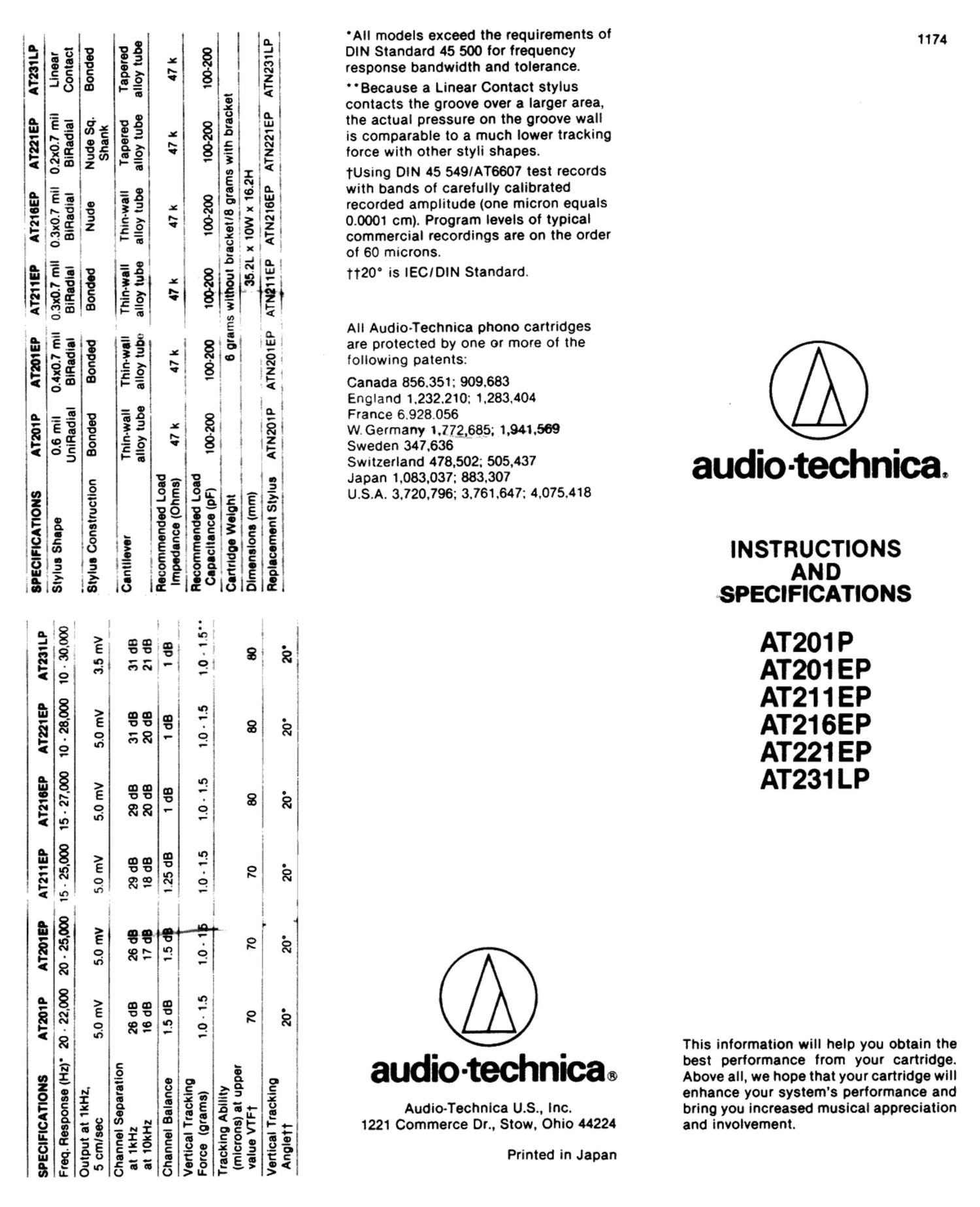
Extracted text from audio technica 231 lp brochure (Ocr-read)
Page 1
AT231 LP
AT221 EP
' 31213:?
0.010.? mil
BiRadial
AT211EP
AT201
0.41:0] mil 0.3x0.7 mil
ATZOIP
0.6 mil
UniRadial
SPECIFICATIONS
A1731 LP
10-33000
AT221 EP
AT211EP AT210EP
15 25.000 15- 27,000 10 - 28.000
AT201
AT201 P
SPECIFICATIONS
Contact
Nude Sq. Bonded
Linear
0.2x0.7 mil
BiRadial
BiFIadIll
Stylus Shape
Freq.fiesponsa(l-iz)' 20- 22.000 20 . 25.000
BlRadlal
Bonded
"Iva-do
Bonded
Bonded
Stylus Construction
Output at 1kl-iz,
5.0 mv . ._ 5.0 mV 5.0 mV 5.0 mv 3.5 mv
5.0 mv
5 cmlsec
Channel Separation
Shank
Tapered
Tapered
alloy tube alloy tube
' Thin-wall
alloy tube
Thinwall
Thin-wa-ll
alloy tube
alloy tube alloy tubu
ThIn-wall
Curtain-1237
31 dB 31 dB
20 dB 21 (18
2908
2068
29 dB
18 dB
28 dB
16 dB
at 1kHz
at 10kHz
~v--.
2605
1708
l I
a.
g 1:1
1 a:
v S 11.2
s 1
s Ial
s2
X ,"
rs 8: 8:1
V f: :z
T 3 'El
3%.: '
«idaI
r~ ~I IN'
I §§2§!E:
5 .o."<:
! E xl
| indium
.- .w
: ggflz'
. s:- 21
5 <
E
4: gig! 9.
r~v' {OI 8:
1 3: : HE
E . ' l
l i i all
:1 g! ; iéi
'l l l 151
l l 1
AD ' l I
83 3A L3?
:55 4: 13.1515;
..
381§§13P18I
€51§§ial§-El
'§§253§|3'§l
SE'§§'S 53-
rz-Ir: IoIEIél
in. é l
0; '- , I
3-. on 8? 8;
'oi '21 1
1 :31 8. 8i
«21 ,
a) "i I a
3 as 3i 8
|
i i
s 2 g
as 0'. El 8
; '
p
3- c'e 2 8
. i 1 I
l a I
s 3! l ,1
'2 c'ai '9: 8}
v-l I
1 z
. a: r
0 g >0 I? E
c-Aga .-
253=;,_|6 I
agefiaus .
339 gig; at
52033532?
0 (9-
283 26:55
o>u i-" > i
'All models exceed the requirements of
DIN Standard 45 500 for frequency
response bandwidth and tolerance.
' 'Because a Linear Contact stylus
contacts the groove over a larger area,
the actual pressure on the groove wall
is comparable to a much lower tracking
force with other styli shapes.
tUsing DIN 45 549/AT6607 test records
with bands of carefully calibrated
recorded amplitude (one micron equals
0.0001 cm). Program levels of typical
commercial recordings are on the order
of 60 microns.
1120° is IECIDlN Standard.
All Audiolechnica phono cartridges
are protected by one or more of the
following patents:
Canada 856.351: 909.683
England 1.232.210: 1.283.404
France 6.928.056
W.Gerrnany 1,772,685; 1.941.569
Sweden 347.636
Switzerland 478.502; 505.437
Japan 1.083.037: 883.307
U.S.A. 3.720.796: 3.761.647: 4.075.418
audio-technical»
Audio-Technlca US. Inc.
1221 Commerce Dr., Stow. Ohio 44224
Printed in Japan
1174
audio-technica.
INSTRUCTIONS
AND
SPECIFICATIONS
AT201 P
AT201EP
AT211 EP
AT21SEP
AT221EP
AT231 LP
This information will help you obtain the
best performance from your cartridge.
Above all, we hope that your cartridge will
enhance your system's performance and
bring you increased musical appreciation
and involvement.
Page 2
INTRODUCTION
The new Audio-Technica Universal Mount
models are low-mass stereo phono car-
tridges designed for either direct plug-in
to P-mount tone arms (both linear track-
ing and pivoted) or. by attaching the in-
cluded adapter. attachment to '/:" on
center universal mounting system tone
arms. To ensure maximum sound quality
from your new cartridge. read and follow
these installation and maintenance in-
structions carefully.
PRELIMINARY INSTALLATION:
P-MOUNT TONE ARM
Following the tone arrn manufacturer's
instructions. carefully line up the four ter-
minal pins on the cartridge and plug the
assembly into the tone arm (make certain
to have removed the mounting screw from
the tone arm). Push the cartridge into the
tone arm as far as it will go and install
and tighten the securing screw (Fig. 1).
Proceed to "FINAL ADJUSTMENTS".
Fig. 1
a
v
PRELIMINARY INSTALLATION:
V: ' UNIVERSAL MOUNT TONE ARM
Following the exploded view illustration
(Fig. 2) begin by removing the stylus and
place it aside for safekeeping.
Using the hardware provided with this
cartridge or the tone arm, attach the
m0unting bracket to the head shell.
(Fig. 2).
Secure with nut
and bolt
Next, attach the four lead wires in the
tone arms head shell to the four pins on
the back of the adapter bracket. Make
certain to follow the color coding (Fig. 3)
for proper connection. DO NOT SOLDER.
The connectors on the wires should slip
over the pins. A pair of small nose pliers
or tweezers are useful for the operation.
Fig. 3
C
at; i
l 2. Left +
('Whltej
RIghl- L
Lori-
w lBIueI
Carefully-align the pins on the cartridge
with the holes in the bracket and push the
cartridge all the way in. Secure with nut
and bolt supplied. Reinstall the stylus
and check for any mechanical interfer-
ence from the mounting screws.
FINAL ADJUSTMENTS
When installing in P-mount linear track-
ing tone arms. the tracking force, except
in special cases. will not have to be ad-
justed. When installing in a V: " universal
mount or pivoted P-mount tone arm. adjust
the tracking force to approximately the
middle of the range shown in the specifi-
cations chart. Tracking force outside the
range can result in increased distortion
and arm-record mm wear.
Other adjustments provided. such as
stylus overhang and anti-skating. should
be set according to the manufacturer's in~
structions for best performance. Because
of its special stylus shape. the anti-
skating adjustment for the AT231 LP
should be adjusted to 1.2 times the track-
ing force. Be certain that the mounting
screws are secure after making the final
adjustments.
ELECTRICAL CONNECTIONS
Run two shielded audio cables from the
cartridgeltone arm to the magnetic phono
inputs on the amplifier or receiver.
Observe left and right channel markings.
A separate ground wire usually comes at-
tached to the turntable, and sh0u|d be
connected to a ground screw found on
the back panel of most electronics.
REPLACEMENT STYLI
Audio-Technica grain-oriented diamond
styli are carefully selected and polished
for minimum wear to themselves and to
your records. However. after an extended
period of play, even the finest diamond
stylus becomes worn. For this reason, it
is best to have the stylus inspected an-
nually. or whenever it appears that wear
or damage may be a problem. The dealer
from whom you purchased this cartridge
can supply genuine Audio-Technica re-
placement styli. Only genuine A-T styli
with the registered circle monogram will
provide the same level of performance.
LIMITED WARRANTY
Audio~Technica brand products purchaso
ed in the USA. are warranted for one
year from date of purchase by Audio-
Technica US. Inc. to be free of defects in
materials and workmanship. in event of
such defect, the product will be repaired
promptly without charge or, at our option.
replaced with a new product of equal or
superior value it delivered to Audio-
Technica U.S.. lnc. prepaid. together with
the sales slip Or other proof of purchase
date. PRIOR APPROVAL FROM A.T.U.S.
lS REQUIRED FOR RETURN. This warran-
ty excludes defects due to normal wear.
abuse. shipping damage. or failure to use
product in accordance with the instruc-
tions. This warranty is void in the event of
unauthorized repair or modification.
FOR RETURN APPROVAL AND SHIP-
PING lNFORMATION. contact the Service
Dept., Audio~Technica u.s.. Inc.. 1221
Commerce Drive. Stow. Ohio 44224.
Except to the extent precluded by ap-
plicable state law; A.T.U.S. WILL HAVE
NO LIABILITY FOR ANY CONSEQUEN-
TIAL. INCIDENTAL. OR SPECIAL
DAMAGES; AND ANY WARRANTY OF
MERCHANTABILITY OR FITNESS FOR
PARTICULAR PURPOSE EXPIRES WHEN
nus EXPRESS WARRANTY EXPIRES.
This warranty gives you specific legal
rights. and you may have other rights
which vary from state to state.