Arp solina schematics

This is the 8 pages manual for arp solina schematics.
Read or download the pdf for free. If you want to contribute, please upload pdfs to audioservicemanuals.wetransfer.com.

Page: 1 / 8
arp solina schematics

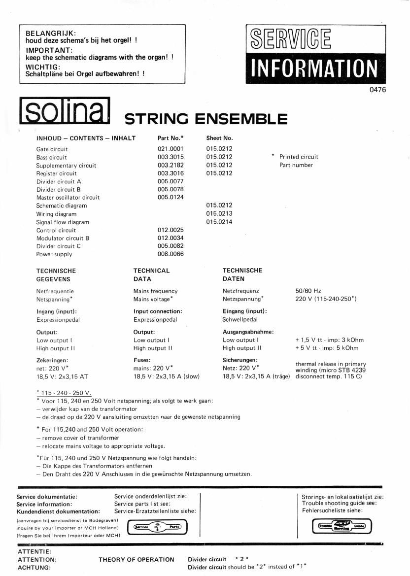
Extracted text from arp solina schematics (Ocr-read)


Page 1

BELANGRIJK: __
houd deze schema's bu het orgel! !
IMPORTANT: _ ,
keep the schematic diagrams With the organ! !
WICHTiG: INF R
Schaltpla'ne bei Orgel aufbewahren! ! .
0476
INHOUD - CONTENTS - INHALT Part No. Sheet No.
Gate circuit 021.0001 015.0212
Bass circuit 003.3015 015.0212 * Printed circuit
Supplementary circuit 003.2182 015.0212 Part number
Register circuit 003.3016 015.0212
Divider circuit A 005.0077
Divider cirCUIt B 005.0078
Master oscillator circuit 005.0124
Schematic diagram 015.0212
Wiring diagram 015.0213
Signal flow diagram 015.0214
Control circuit 012.0025
Modulator circu1t B 012.0034
Divider circuit C 005.0082
Power supply 008.0066
TECHNISCHE TECHNICAL TECHNISCHE
GEGEVENS DATA DATEN
Netfrequentie Mains frequency Netzfrequenz 50/60 Hz
Netspanning" Mains voltage* Netzspannung'E 220 V (115»240-250*l
lngang (input): Input connection: Eingang (input):
Expressnonpedal Expressionpedal Schwellpedal
Output: Output: Ausgangsabnahme:
Low output | Low output l Low output I + 1,5 V tt , imp: 3 kOhm
High output ll High output N High output II + 5 V tt - imp: 5 kOhm
Zekeringen: Fuses: Sicherungen: thermal release in pr'
_ * . _ a . i, Imary
net. 220 V mains. 220 V Netz. 220 V winding (micro STE 4239
18,5 V: 2x3,15 AT 18,5 V: 2x3,15 A (slow) 18,5 V: 2x3,15 A (trage) disconnect temp. 115 C)
*115-2407250V.
* Voor 115, 240 en 250 Volt netspanning; als volgt te werk gaan:
- verwijder kap van de transformator
7 de draad op de 220 V aansluiting omzetten naar de gewenste netspanning
* For 115,240 and 250 Volt operation:
- remove cover of transformer
2 relocate mains voltage to appropriate voltage.
*Fur 115,240 und 250 V Netzspannung wie folgt handeln:
- Die Kappe des Transformators entfernen
7 Den Draht des 220 V Anschlusses in die gewiinschte Netzspannung umsetzen.
Service dokumentatie: Service onderdelenlijst zie: Storings» en Iokalisatielijst zie:
Service information: Service parts list see: Trouble shooting guide see:

Kundendienst dokumentation: Service-Erzatzteilenliste siehe: Fehlersucheliste siehe:

iaanvragen bij servicedienst ta Bodegravenl 72
a
inquire by your importer or MCH Holland) let u;- hm

(fragen Sie bei lhrem lmporteur oder MCH)

ATTENTIE:
ATTENTION: THEORY OF OPERATION Divider circuit * 2 *
ACHTUNG: Divider circuit should be *2" instead of *1*

Page 2

IIIA/ '

DEMONTAGE STRING-ENSEMBLE

. Verwijder schroeven |

.TiI bovenblad op, ZIe ||

.Schuif bovenblad weg, zie III

. Verwijder schroeven IV

. De konstruktie kan nu uit de kast
worden getild.

6. De panelen A en B zijn kIapbaar na

verwiidering van schroeven VI en V

014>wm--

DISASSEMBLY 0F STRING-ENSEMBLE

. Remove (3) screws I

. Raise cover, see ||

. Push cover out of the way, see III

I Remove (4) screws IV

I Lift out unit from cabinet

.PaneIs A and B will fold out of way
after removing screws V and VI .

070113de

-V

DEMONTAGE STRING-ENSEMBLE

.Schrauben rausdrehen (siehe I)

.Oberbrett anheben (siehe II)

. Oberbrett wegschieben (siehe Ill)

.Schrauben rausdrehen (siehe IV)

. Die Konstruktion kann jetzt aus der
Kiste gehoben werden.

6. Die PaneeIen a und b sind klappbar,

nachdem die Schrauben rausgedreht

sind. Isiehe V und VI).

(3&de

II

It; 9 7 5 3 GATE
I 8' TO 8 5 4 IC
PANE
SIGNALS FRIOM DIVIDERS CIRCUITS
4' a' 4' e' 4' 8' I. a' z. a-
I] I] D D I] I] [I [I U I]
c,_ o,x 0,. F2 5; G3 Fg-r A4 64-, c5 KEVGATES
VI
PANEL B
TONES' 13 muss:
G F
I:
E F
D
05
:1
D c" m

POWER SUPPLY MODULATOR CIRCUITS

CONTROL CIRCUIT

DIVIDER CIRCUIT

DIVIDER CIRCUIT MASTER OSCILLATOR

1n Hal- Hal- «3* *24 *Zas Ian
I ,W, ,,,,,,,, v, , A7 , WWV 7,7, ,fi Y
PANEL C

EXP OUTI
FED.

00 1%
TR.0UT 6. ur

REGISTER CIRCUIT BASSCIRcun DIVIDER CIRCJ

*3:

«he

«29!