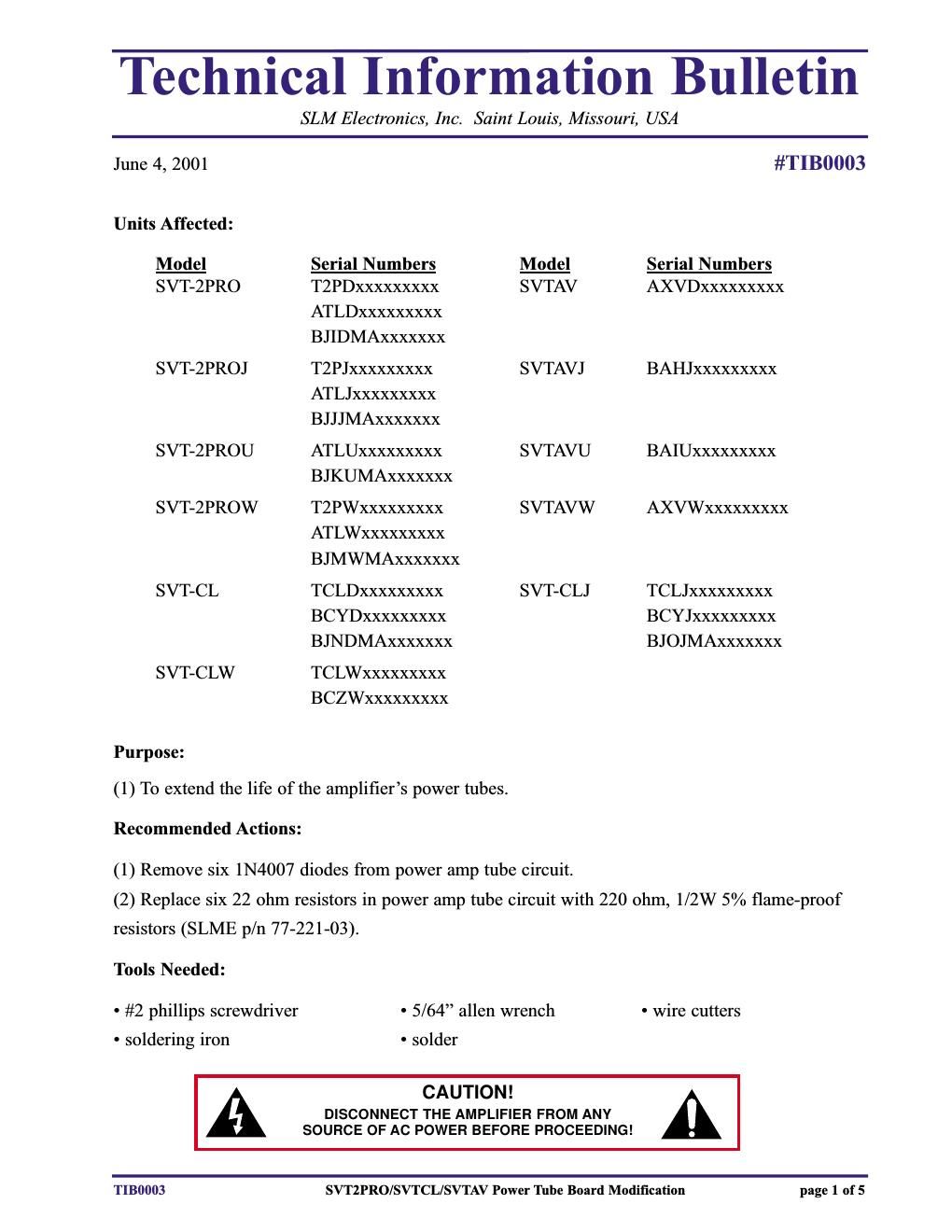
Ampeg svt tube life modification information

This is the 5 pages manual for ampeg svt tube life modification information.
Read or download the pdf for free. If you want to contribute, please mail your pdfs to info@audioservicemanuals.com.

Page: 1 / 5
left right
ampeg svt tube life modification information

Extracted text from ampeg svt tube life modification information (Ocr-read)


Page 1

Technical Information Bulletin SLM Electronics, Inc. Saint Louis, Missouri, USA Corrective Action: SVT-2PRO: (1) Place the amplifier on the work surface, right side up, front panel facing you. (2) Remove the 12 screws from the top cover. Remove the top cover and set it aside. Proceed to step 7. SVT-CL/SVT-AV: (1) Place the amplifier on the work surface, on one end, cabinet bottom facing you. (2) Remove four of the five large bolts from the bottom of the cabinet, leaving the upper bolt in place. (Refer to the adjacent picture.) (3) Lower the amplifier onto its feet on the work sur- face. Position the amplifier so the end with the remaining bolt hangs over the edge of the work sur- face. (Refer to the adjacent picture.) Remove the remaining bolt from the bottom of the cabinet. (4) Reposition amp on work surface, right side up, front panel facing away from you. (5) Remove the seven screws from the rear grille screen. Remove the screen and set it aside. (6) Slowly and carefully work the amplifier assembly about 2/3 of the way out of the cabinet -“ far enough to allow access to the tubes and the tube board. Avoid putting excessive strain on the con- necting cables! (7) Grasp one of the power tube retainers by its top ring. Lift the retainer up and away from the power tube, then slowly lower it to the plate at the base of the tubes as shown in the adjacent pictures. Repeat for the remaining tube retainers. TIB0003SVT2PRO/SVTCL/SVTAV Power Tube Board Modification page 2 of 5

Page 2

Technical Information Bulletin SLM Electronics, Inc. Saint Louis, Missouri, USA CAUTION:The tension on the retainers springs may cause them to snap back towards the base of the tubes, possibly cracking their glass casings - slowly lower each retainer down to the base of the tubes to avoid such damage. (8) Carefully remove each of the power tubes by gently rocking it side to side while lifting it straight up. Set the tubes aside. (9) Each tube retainer is secured to the tube socket with two 5/64 allen head screws. Remove the screws, then remove the tube retainers and set them aside. (10) Remove the eight screws from the tube plate. Remove the tube plate and set it aside. (11) Lift the power tube circuit board assembly up slightly and disconnect the white two-wire connector from the two-pin header on the edge of the board as shown in the adjacent picture. (12) Lift the tube board assembly further up until the ribbon connector beneath it is accessi- ble. Disconnect the ribbon connector from the multi-pin header on the circuit board beneath as shown in the adjacent picture. (13) Disconnect the remaining five wires from the underside of the tube board assembly. Place the tube board assembly on the work surface so the printing reads right side up. (14) Locate, cut and remove the six 1N4007 diodes (D1, D2, D3, D7, D8, D9) from the tube board. (These are located in the high- lighted areas of the adjacent picture.) (15) Locate, desolder and remove the six 22 ohm resistors (R2, R4, R6, R7, R9, R11) from the tube board. (These are also located in the highlighted areas of the adjacent picture.) TIB0003SVT2PRO/SVTCL/SVTAV Power Tube Board Modification page 3 of 5