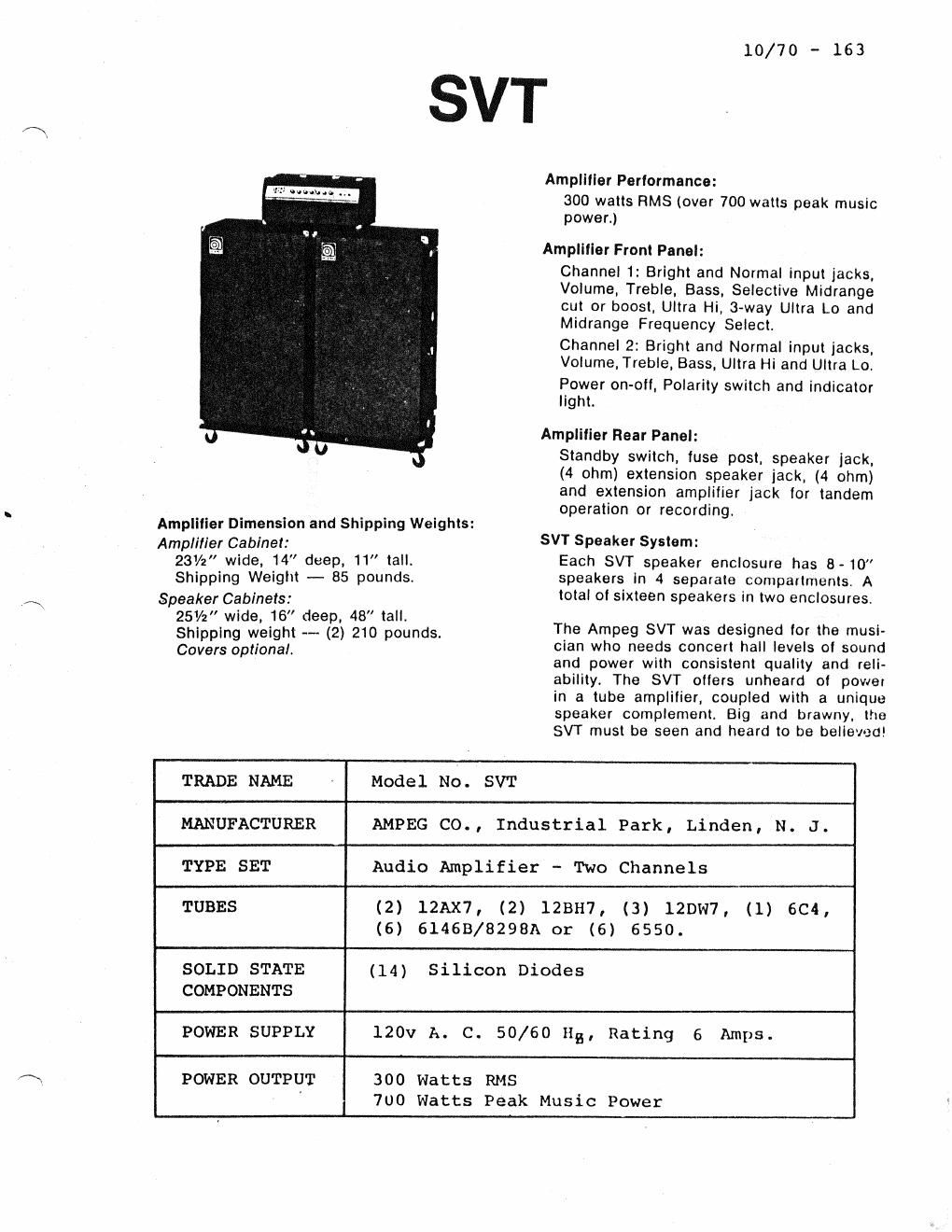
Ampeg svt 10 70 service manual
This is the 7 pages manual for ampeg svt 10 70 service manual.
Read or download the pdf for free. If you want to contribute, please upload pdfs to audioservicemanuals.wetransfer.com.
Extracted text from ampeg svt 10 70 service manual (Ocr-read)
Page 1
svr 1° "
Amplllier Perlormance:
300 watts RMS (over 700 watts peak music
power.)
Amplllier Front Panel:
Channel 1: Bright and Normal input jacks,
Volume, Treble, Bass, Selective Midrange
cut or boost, Ultra Hi, 3-way Ultra Lo and
Midrange Frequency Select.
Channel 2: Bright and Normal input jacks,
Volume, Treble, Bass, Ultra Hi and Ultra Lo.
Power on-oll, Polarity switch and indicator
light.
Amplitier Rear Panel:
Standby switch, (use post, speaker jack,
(4 ohm) extension speaker jack. (4 ohm)
and extension amplilier jack for tandem
operation or recording.
Amplifier Dimension and Shipping Weights:
Amplifier Cabinet: SVT Speaker System:
23%" wide, 14" deep, 11 tall. Each SVT speaker enclosure has 8-10
Shipping Weight - 85 pounds. speakers in 4 separate compartments. A
speaker Cabinets: total ol sixteen speakers in two enclosures.
1 r/ - u n
éifipgrédfigigt fag.) go Sggnds. The Ampeg SVT was designed (or the must.
Covers optional. ctan who needs concert hall levels of sound
and power with consistent quality and reli'
ability. The SVT otters unheard ol power
in a tube amplilier, coupled with a unique
speaker complement. Big and brawny, the
SVT must be seen and heard to be believed!
TRADE NAME « Model No. SVT
MANUFACTURER AMPEG C0., Industrial Park, Linden, N. J.
TYPE SET Audio Amplifier ~ Two Channels
TUBES (2) 12Ax7, (2) 12BH7, (3) lZDw7, (1) 6C4,
(6) 6146B/8298A or (6) 6550.
SOLID STATE (14) Silicon Diodes
COMPONENTS
POWER SUPPLY 120v A. C. 50/60 I15, Rating 6 Amps.
POWER OUTPUT 300 Watts RMS
700 Watts Peak Music Power
Page 2
10/70 - 173
SVT SERVICING AIDS
BLOWS FUSES - (1) Standby Switch Off: a) Bad filament Transformer.
b) Shorted A.C. wiring. c) shorted Tube Socket Pins. (2) figggggx
Switch On: a) Shorted A.C. wiring after Standby Switch. b) De-
fective Power Transformer. c) Defective D3-Dl4 Diodes. d) Failure
of negative bias circuit. (See that you read -47 volts at Pin 85
of 6146 Tube.) e) Defective 6146 Tube or Tubes. f) Defective Out-
put Transformer. g) Defective Filters - 010, C12.
LOSS OF POWER - (1) Weak Tubes. (2) Check all 10 ohms/5 watt Plate
Resistors if any of these have open circuited, replace the associ-
ated 6146 Output Tubes. (3) Check all 22 ohms/l watt grid
Resistors. (4) Check the two 1 ohm/1 watt Cathode Resistors.
(5) Defective D1 - D2. (6) Misadjustment of bias and or balance
Controls. (7) Bad Plate Cap Connectors.
OSCILLATION WITH CONTROLS ADVANCED (on early versions). See that
the shielded cable is grounded at the P.C. Board rather than at the
Input Jack Channel #2 assembly.
CHECK THE TROUBLESHOOTING CHART PART #4010086 FOR MORE HINTS
CAUTION: WHEN SERVICING SPEAKER CABLE BE CAREFUL OF THE 120V
A.C. ACROSS PINS 2 AND 3 OF THE CONNECTOR. THIS
FEATURE 15.3 SAFETY AMPLIFIER IHTERLOCK.
POWER AMPLIFIER CHASSIS LAYOUT
FILAHENT
FRANSFORMER
GD
1211107
® 8
E
E g 1213117 12mm :5
2 g a
:z
a 0
® ®
OW
61463 61463 61468 6146B 61463 6146B
CONNECTOR P2