Altec man 1568 a owners manual
This is the 4 pages manual for altec man 1568 a owners manual.
Read or download the pdf for free. If you want to contribute, please upload pdfs to audioservicemanuals.wetransfer.com.
Extracted text from altec man 1568 a owners manual (Ocr-read)
Page 1
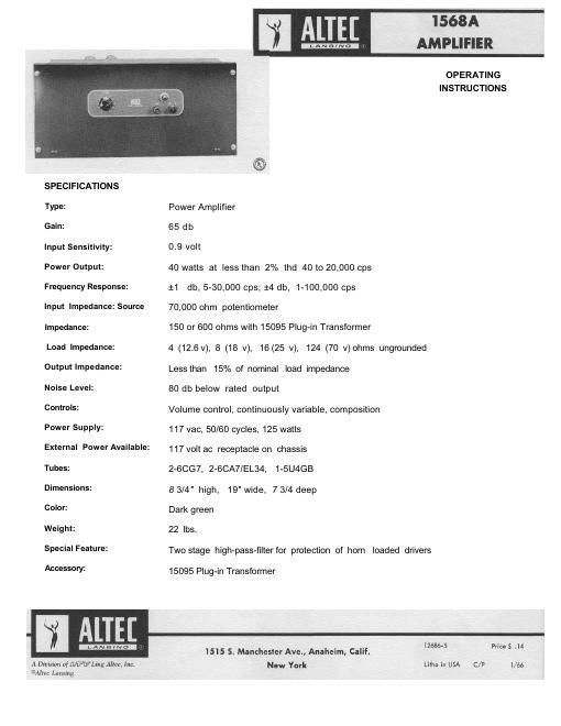
GENERAL DESCRIPTION The 1568A Amplifier is a rack mounted, AC operated power amplifier intended for use in sound reinforcing, paging, music distribution, or any application requiring low distortion, wide frequency range, complete stability with any type of load, reliability of operation, ease of servicing or low cost. At 40 watts distortion is less than 2% at any frequency from 40 to 20,000 cycles per second. The frequency response is within 4 db of mid range value from 1 cycle per second to 100 KC. The feedback circuit is designed for stability under conditions of varying line voltage, varying tube characteristics, and all types of loads including long unloaded speaker lines having considerable capacitance. The tubes are conservatively operated under CCS (con- tinuous commercial service) ratings of their manufacturer, and the amplifier has been shown to withstand "hot switching" and other punishment which might be encountered in the hands of untrained operators. The amplifier occupies five units of rack space (8 3/4") and has a hinged front panel on which are mounted the power switch, fuse, pilot light and a continuously variable gain control. All circuitry is completely acces-sible for servicing when the front panel is open. The amplifier is equipped with a 3-wire power cord terminating in a 3-pin cap. Input and output terminals are provided in the form of barrier-type terminal blocks mounted on the outer surface of the chassis. INPUT CONNECTIONS The 1568A Amplifier is equipped with two pairs of input connections. Terminals 1 and 2, connecting directly to the input potentiometer, are provided for unbalanced high impedance sources, and to bridge unbalanced low impedance lines having a signal voltage of 0.9 volt or higher. Terminals 3 and 4 connect to a standard octal socket which accommodates the accessory plug-in transformer. With the 15095 Transformer, balanced or unbalanced lines of 150 or 600 ohms up to a level of +15 dbm may be connected to input 3-4. The octal socket is normally connected for 500/600 ohm operation; 150 ohms impedance may be obtained by strapping the terminals in accordance with the diagram shown on the schematic. OUTPUT CONNECTIONS Outputs accommodate nominal loads of 4, 8, 16 and 1 24 ohms, the corresponding full-drive output voltages being 12.6, 18, 25 and 70 volts. Speaker Matching: Use the output tap which most nearly equals the total speaker impedance. If the load im- pedance falls between two output terminal values, favor the terminal of lower impedance. 70 Volt Line: The 70 volt distribution system permits connection to a large number of speakers, each to operate at its own power level as required, without the necessity for computing impedances. In this system each speaker is equipped with a transformer containing a number of taps rated in terms of power, and the tap is selected which gives the power desired for that speaker. The total of the power settings for all speakers should be equal to or less than the amplifier system power rating. The 1568A Amplifier is equipped with outputs to drive both a 70 volt line and a 25 volt line. Protection of Horn Loaded Drivers: Driver loudspeakers coupled to horns are used in paging or voice reinforcing systems where excellent intelligibility is required in the presence of high noise levels, effects of wind, and other disturbances. When a loudspeaker system dividing network is not available the diaphragm of the driver loud-speaker may be protected from low frequency power by the use of the R-C low frequency cut-off filter in V1 grid circuit (see schematic). As shipped, capacitors C1 and C2 are strapped out. By cutting one or both of these straps attenuation is introduced as shown in the table, depending upon the impedance of the source. Effect of High Pass Filter Source Strapping 250 500 1000 2000 cps Impedance 100,00 ohms One strap cut - 6.5 - 3 - 1 - 0 . 2 d b Both straps cut - 1 6 - 8 - 3 . 5 - 1 . 2 d b Low One strap cut - 1 3 - 8 - 3 . 5 - 1 . 2 d b Both straps cut - 2 2 - 1 2 - 4 . 2 - 1 . 5 d b CONTROLS The only controls on this amplifier intended for normal operation are the power switch and the gain control. Potentiometer P2, which establishes the bias voltage for the output tubes, is set at the factory and will probably not require readjustment over a long period of operation. If, due to ageing of the rectifier, the bias voltage should drop below the value indicated on the schematic, it will be desirable to reset P2. Measurement should be made with an accurate voltmeter, at a line voltage of 117 volts, and with no signal applied.