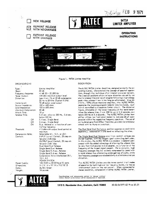
Altec 9473a compressor
This is the 5 pages manual for altec 9473a compressor.
Read or download the pdf for free. If you want to contribute, please upload pdfs to audioservicemanuals.wetransfer.com.
Extracted text from altec 9473a compressor (Ocr-read)
Page 1
DEE]
NEW RELEASE
REPRlNT RELEASE
WITH NO CHANGES
REPRlNT RELEASE
WlTH CHANGES
i
9473A
LIMITER AMPLIFIER
AlTEE
8 LAlJSlluLfi-
OPERATING
INSTRUCTIONS
as: .u
SPECIF lCATlCNS
Type:
Gain:
Frequency Response:
Jamar Onlpm:
D islorl I an:
Noise Level:
Source Impedance:
Load Impedance:
Maximum Campressicn:
Ariack Time:
Release Time:
OR
OR
OR
Threshola:
Compression Ratio:
Controls:
Power Saaply:
D imens inns:
Cclor:
Wei gm;
Figure 1. 9473A Limiler Amplilior
Limiter Amplifier
50 d3
:1 dB 20 ~ 26,000 Hz
+24 dBm maximum aufpul level
Less ll'icn WE c1920 dB comp'csslnn
32 Hz lo 20 KHz (Typical 0.5%)
74 dB belaw ruled output
150 a: 600 ohms
l50 or 600 ohms
40 dB
10 ps
CA sec. above 250 Hz; 3.6 sec.
below 250 Hz
0.4 sec. Single Band
3.6 sec. Single Band
Deal Release as a «unciian of con-
Polling reauancy
+33 dBmwltl avipul level control al
maximum
Selecmble 4:], 12:1, or ZOzl
lNPUl Le vel Camrol' 20 siep ai-
renuaiar 2 dB/srep
OUTFUY Level Carmel, 20 step a?-
tenualar 2 d3/ step
Dual Band Dual Release
Single Band Dani Zelease
Single Bané 0.4 sec . Release
Single Band 3 .6 sec . Release
Compression Rario lnierlocked '20:l ,
3:3 , 4:?
POWER SWlTCH
lBO/ZAOV a: 30/60 Hza: l5 watts
54/4" H x l? Wx 7-3/16 D
ALTEC Gui"
14 pounds
1515 5 Manchester Ave., Anaheim, Calif. 92803
DESCRaFTION
TlxeALTEC 9473A L'miia' Amplilier,designeed primarily Farre-
cording studios, :lraracrerizes the cancapr of spociral supera-
rlcn, through the technique sf ah infernal crasscwer network.
The classical problems of en ve lope distortion named by ran
shorf a when rims and lbs; of aragram follnwinga lug'n energy
peak when release l' me is too long are eliminaieav A wild-
: ra ie , 30% silken fransistvr amplifier, ll~e ALTEC 9473A,
separates the incoming program marerlal inro rwa bond). éocl
ha nd corirrolled my a separaie limive circuit, The disramor
figure, allowable at five lowest irecuency of the? band defor-
mines-41: release time, from 250 Hz up a 0.4 seconds, are
below 250 Hz at 3 .6 secands. The ALTEC 9473A Limiler Am-
plifier utilizes fwo ronr panel memrs la indimre dB of com-
prcssion within flue respecrive Frequeny spectrum. The use of
an insalaled gar: Field Ellec Transisfarmrofides lnsranranewe
atrack wish no thump or aversi-aan
The Dual Band Dual Re lease posilion aparuras an eaeli ham
separweiy, compression 3': one band not afieceing Use arms: .
The Single Band Dual Release posi Hon conrrcl voltages are
W957 signal cantmiling both rides.
In his m ed e , rhe ALTEC 9473A is a smndard wideband cam-
pressar with line added advanlage of allawing fine release firm:
in vary frarr 0.4 seconds to 3K: secynds, as a luncrian 0 rlic
frequency of the largest signal preseni. For example , lugh
frequency passages may be :everely compressed by peazrvwiib
a rapid release rlsus eliminal-ing prolonged I05: af audie, wail:
law Frequency pamgesure released slowly 1c eliminare envelape
dixfortion.
va ALTEC 9473A Limllen provide fierce control Zr- all modes
of operarion for bath higlmnd low reauenny bands, via slexeo
inlercanmc! jack: on the ear panel . When canneclad Fo'
starve operation, compression in cilhar ALTEC 9A73A Limim,
Spofification! nmd computer. "him a; alarms: wiiiwul
nah. Oman xxx-lawman will u maintained or improved,
42-02-O-l1897-02 Price $0 . Zl
Page 2
will dousea corresponding degree at comoression in the other,
theregy maintaining channel gain balance. Well positioned
controls provide unobstructed vison for ease of operation, and
a hinged front panel Facilitates sorvrcing.
INSTA LLATlON
The ALlEC 9473A limiter Amelitier will Flesh mount into any
stand-3rd I9 rock ercabinet rack and requires only three verti-
cal mourting spaces (5-1/4") and is 7-3/l6 deep.
A screwtype terminalblaek is provided at the rear of the chossls
:07 inpvl and output connections. Stereo cont-ml in all moon
of operation tor high and low frequency bondsare provided via
the stereo interconnect [asks also on the rear of the chassis.
Terminals b, 7, B, and 9, located on the input side at the ter-
minal strip provide crop" termination For i50 at Q00 ohm driving
source. Strapping combinations and input connections are dia-
grumrned in Figure 3.
Yerminols 1, 2, 3, and A on the output terminal str lp are for
Dads at 150 or 600 ohms. Proper strapping combinations and
output connections are oiagrommed in Figure 3.
Figure 2. Rear View 9473A Limiter Amplifier
APPLICATFON
The ALTEC 9473A LimitorAmplitierisintenaed For use in auto-
matic level control applications fulfilling the requirements of
professional broadcast, recordingand motion picture industries.
Figures 4 and 5, illustrate two at several system arrangements,
Figure 4 illust-atcs the use of the 9473A Limiter Amplifier in
controlling peak levels from live recording mlcrophones in a
typical resorting studio applicatiani eliminating system over-
drive in the rope recording urit.
Figure 5 illustrate; the 9473A LimiteyAmplitlerused in a typi-
cal broadcast studio application to peak limit the signal from
the program mixing console prior to distribution to the trans-
mittor moduletor. This allows the station to operate with high
modulation efficiency while preventing over modulation. The
9473A Limiter Amplifier proviaes an output of +24 6% For
driving remote lines to the modulator.
OPERAIION AND USE OF CONTROLS
The input levelcontrol is used to odgust degrees of limiting with
varying input levels. With the control in the Fully clockwise
position (0), limiting takes place with on input at -35.
The input level required to reach limiting threshold Increases
2 dB For every countercloekwisa pas itior c the input level
control tr: amoxlmum of) d3, 6.5.; an input of t5 dBrn. The
output level control adiusts the output from the limiter over a
40 65 range. With the output level control set lolly clackwile
(0), on input signal causing threshold, produces an output of
+15d5m. This output may bereduead 2 at! par counterclockwise
step of the output level control for a maximum of 40 dB, i.e.;
-25 dBm output at threshold .
COMPRESSION AND RATIO CONTROLS
The 20:], l2:l a nd 4:1 compression ratio controls are used to
change the transferslope of the Iinriterabave limiting threshold
In the 20:1 position a 20 dB increase in the input level above
threshold causes only l :13 increase in the output . The slope i1
l2:l or 4:1 in the other two positions, respectively.
*MINM trauma" -um. woven-Vt
uwm manna mm. 1w
!l7ll Ii'lll t~tss \21735
t
9 o 00? a
.
mi, lama! {W27}
L: u ~
kJ
q
Figure 8. Input and Output Strapping
SINGLE AND DUAL BAND RELEASE FUNCTIONS
In the Dual Ba'ld, Dual Release position, the limiter operates
on pact band separately, compressior in cne baud not affecting
the other.
In the Singlefiand, Dual Release position, the control voltage;
enslaved together with the largatsignal controlling hath rides.
in this mode the limiter is attendant widebond compressor with
release time varying from 0.4 seconds to 3 .6 seconds, as a
function of the frequency ol the largest signal present.
In the Single Band 0 .4 second release or Single Band 3 .é re!ease
positions the limiter operates as a standard widebano' limiter,
with a release timeof 0.4secortdso: 3.6seconds, retpecrzvely.
CALlBkATICN PROCEDURE
1 . See Figure 6 for location at controlsand sireotionofroto-
lion. Thoarrm inclicate the directior at rotation toward
maximum on each central.
Sol HIGH and LOW BAN D LINEARITY controls to their
MIN. positions.
3. Set HIGH and LOW BAND SENSITIVlTY controls to their
MID. positions.
Set HlGH and LOW BAND THRESHOLD controls to Meir
MIN. positions.
Set tNPUT level control to 0.
Set OUTPUT level control to l2.
Push the 12:1 COMPRESSlON RATIO selector switch.
Simultaneouslyptoss the DUN. BAND DUAL RELEASE and
SINGLE BANDOASEC . RELEASE buttoml thereby locking
both down . Jumper paint A to point B. (See Figure 9 for
location).
mNV-UI