Altec 9440a service info

This is the 12 pages manual for altec 9440a service info.
Read or download the pdf for free. If you want to contribute, please upload pdfs to audioservicemanuals.wetransfer.com.

Page: 1 / 12
altec 9440a service info

Extracted text from altec 9440a service info (Ocr-read)


Page 1

CAUTION N0 riser-si'rvicmbtr parts IttSIdt. Hazardous voltage may Ih' en-
muntmd within the rhassrs. Installation and Smart information
tut thin this document is for use only by ALTE C sound contractors. factory authorized

warranty stations and qualified sciatic:r personnel.

II as! cnaint it t'utilisatmr dc m' is r' n'r Iiu-mZmc Its iia's
IMPORTANT: . , . p . q," . 0

mtvrm's dc iapparerf. tics Commits a hantr tvnsmn pnuvant pas-
ser a I'inférieur an (Iiéssrs. Les ronsergncmcnts mcIus «inns cc document sent destinés
uniqnmwnt a i'usage' tics installaicurs agréés dos systémvs arousiiqiws ALTEC, (II'S

centre; de reparation sans garantii' autarisés. ainsi qm. an personnel dmtrvtimr

quatifié.

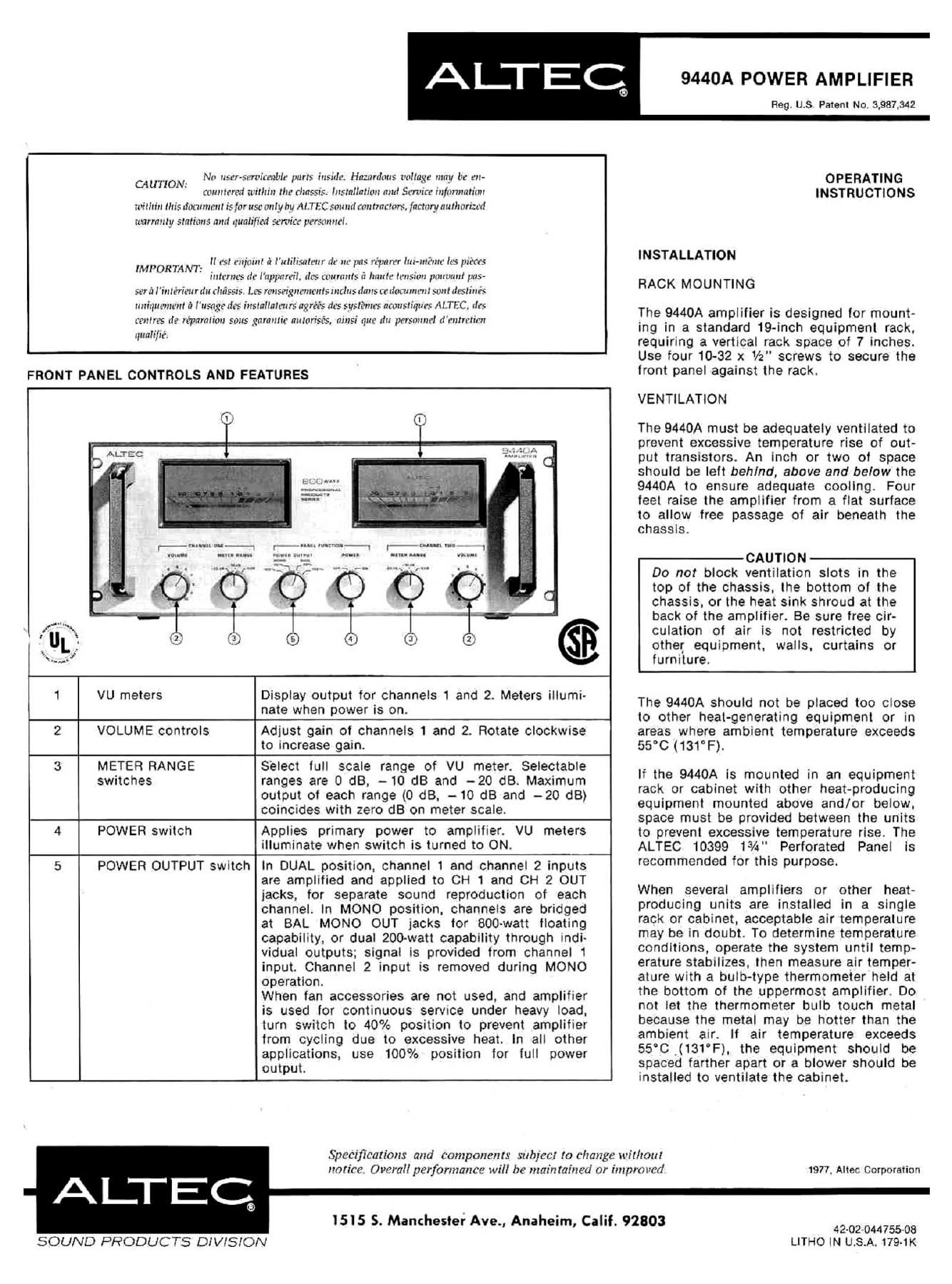
FRONT PANEL CONTROLS AND FEATURES

1 VU meters

Display output for channels 1 and 2. Meters illumi-
nate when power is on.

2 ' VOLUME controls

Adjust gain of channels 1 and 2. Rotate clockwise
to increase gain.

3 METER RANGE
switches

Select lull scale range of VU meter. Selectable
ranges are 0 dB, - 10 dB and -20 dB. Maximum
output of each range (0 dB, - 10 dB and -20 dB)
coincides with zero dB on meter scale.

4 POWER switch

Applies primary power to amplifier. VU meters
illuminate when switch is turned to ON.

5 POWER OUTPUT switch I

In DUAL position, channel 1 and channel 2 inputs
are amplified and applied to CH 1 and CH 2 OUT
jacks, for separate sound reproduction of each
channel. In MONO position. channels are bridged
at BAL MONO OUT jacks for BOO-watt floating
capability, or dual ZOO-watt capability through indi-
vidual outputs; signal is provided from channel 1
input. Channel 2 input is removed during MONO
operation.

When fan accessories are not used, and amplifier
is used for continuous semce under heavy load.
turn switch to 40% position to prevent amplifier
from cycling due to excessive heat. In all other
applications, use 100% position for full power
output.

L _

SOUND PRODUCTS DIVISION

1515 5. Manchester Ave., Anaheim, Calif. 92803

9440A POWER AMPLIFIER

Reg. US Patent No. 3,987,342


OPERATING
INSTRUCTIONS

INSTALLATION
RACK MOUNTING

The 9440A amplifier is designed for mount-
ing in a standard 19-inch equipment rack.
requiring a vertical rack space of 7 inches.
Use four 10-32 x 1/2 screws to secure the
front panel against the rack.

VENTILATION

The 9440A must be adequately ventilated to
prevent excessive temperature rise of out-
put transistors. An inch or two of space
should be left behind, above and below the
9440A to ensure adequate cooling. Four
feet raise the amplifier from a flat surface
to allow free passage of air beneath the
chassis.

CAUTION

Do not block ventilation slots in the
top of the chassis, the bottom of the
chassis, or the heat sink shroud at the
back of the amplifier. Be sure free cir-
culation of air is not restricted by
other equipment, walls. curtains or
furniture.

The 9440A should not be placed too close
to other heat-generating equipment or in
areas where ambient temperature exceeds
55°C (131°F).

If the 9440A is mounted in an equipment
rack or cabinet with other heat-producing
equipment mounted above and/or below,
space must be provided between the units
to prevent excessive temperature rise. The
ALTEC 10399 13A" Perforated Panel is
recommended for this purpose.

When several amplifiers or other heat-
producing units are installed in a single
rack or cabinet. acceptable air temperature
may be in doubt. To determine temperature
conditions, operate the system until temp-
erature stabilizes. then measure air temper-
ature with a bulb-type thermometer held at
the bottom of the uppermost amplifier. 00
not let the thermometer bulb touch metal
because the metal may be hotter than the
ambient air. If air temperature exceeds
55°C _(131°F), the equipment should be
spaced farther apart or a blower should be
installed to ventilate the cabinet.

Specifications and components subject to change wit/rout
notice. Overall performance will be maintained or improved.

1977, Altec Corporation

42-02044755-08
LITHO IN U.S.A. 179-1K

Page 2

REAR PANEL CONNECTIONS AND FEATURES

-


4
ALTEC arcs-t:
...... . .
0 .000.0.0.0.0.0.o.. 0 ,cum wantcts Most-s" . .0"0'0'00.0'0'0'0b. .
.0.°.'.0.......,,.. ,00000000000000
emu-Laur- 0000000000000000
00000000000000000. .00000000000000000 A
000000000000003000 umuuuu 000000500000000000 cont-an» 5v
'.°.'.°.0.'0.0...°....° :0000000000000000000 nm-ouuo- .
0 0 V 0 0 '00 :00000000000000000000
.OCOOOCOCOCCOOOUUOOCO ..................... DIM!" ID 5
0.0.0.000'°000000000 0000000000000000000000 nos-mur-
........... ............ ............. ........
30.0.0.0: 0.. 0.3-; '{ggg'gggg :000000000000009000 0000 WM" '0 3'
"0000.005 000.0 0.00 . . 3....,....'.°.'.°..°.O.0. '0.0.0.0.0.0.0 Din-0005316
.°.'.0...0.'.-35......3. 00000000000000000000000
......... ..... 0000000000000000000000
. 00000000000000000000000
°'°°"°°°° 0000000000000000000000
.000000000000000000000. ....................
00000000000000000000 ,............". ..
can um. °"°°"°"" 0000000 uo0000000'0
um \0000000000000000000 000000000000 0 00
,0 0000000000000000'60 cuun ........... 00. 000
m m """"° avg-won» 0000000000'0'0 .. l
\00000000000000 we ,........... uonomvuv
\00000000000' .........., mailman
new 3 OICAOOP' 00m. 0 .....- O locuvonu
r '91
-- W0 0 MAUI! I. UN. W U 1 ml! 1 mm
m. l1 misowfl remnant rel! cunt-cu! 00h Fm 0007 rem can run

I
"

., 6
ti if


Fuse

Protects amplifier from excessive current drain.
Replace only wlth same type 10-ampere fuse. Refer
to qualified service personnel if fuse blows re-
peatedly. A 15-ampere fuse may be used for test
purposes only.

SWITCHED AC
OUTLETS

Provide auxiliary line voltage. turned on by POWER
switch on front panel. Total current from both
outlets limited to 1.5A by internal fuse.

CH 1 OUT
CH 2 OUT
speaker terminals

Connect channel 1 and channel 2 speakers for
corresponding channels. Two pair of standard GR
jacks have red (+) and black (-) polarity designa-
tions. When two or more speakers are connected
in parallel, combined impedance should be not less
than 4 ohms.

BAL MONO OUT
speaker terminals

Connect balanced output to speaker system. NEVER
CONNECT EITHER TERMINAL TO GROUND. When
two or more speakers are connected in parallel.
combined impedance should be not less than 8
ohms. Operate POWER OUTPUT switch in MONO
mode.

TO ADD AMP jacks

Accept cables to connect another 9440A amplifier
in parallel.

UNBAL INPUT jacks

Accept cables from high-Impedance (nominal 15KQ)
microphones, AMIFM tuners. tape recorders. etc.

If the 9440A amplifier becomes too warm,
due to continuous use at high output. two
accessory fans should be installed on the

BAL HIGH 2 INPUTS
receptacles

Accept cables from high-impedance (nominal 15KQ)
microphones, AM/FM tuners, tape recorders. etc.
Two transformer-isolated. balanced input channels
have XLR3-31 type connectors.

240 volts. as shown in Figure 1.

rear of the heat sink shroud. Each fan show the appropriate side
should produce at least 30 cubic feet per connections.
minute at a static pressure of 0.04 inch of
water. Fans provided in the ALTEC Model mm
105878 Fan Kit meet this requirement.

P H
ELECTRICAL

0 G
120-Volt. 50/60 Hz Power Connections

N 7
Equipment supplied for domestic use ls
provided with the power transformer pri- G
mary strapped for 120 volts. as shown in
Figure The power input nameplate, L °
adjacent to the power cord on the chassis, K c
is mounted to show the appropriate side
specifying connections. Verify that line 4-5 a
voltage is in accordance with the voltage g
rating before connecting primary power. .[j 1 ..

240-Volt, 50/60 Hz Power Connections

Export equipment

REAR
STRAPPING F0? 170!

is provided with the
power transformer primary strapped for

__). -

G

power input nameplate. adjacent to the
power cord on the chassis, is mounted to
specifying

Figure 1. Strapping of Power Transformer

For a 9440A previously wired for 120 volts
ac primary power. use the following pro-
cedure to change wiring for 240 volts ac
operation. Refer line voltage change to
qualified service personnel only.

Step 1. Turn POWER switch to OFF.

Step 2. Remove power cord from primary
power outlet.

Step 3. Remove seven screws securing
top cover. Lift off top cover to
expose transformer terminal
board.

Step 4. Locate strap connecting terminals
C and F (see Figure 1). Remove
strap and store for possible later
use.

Step 5. Locate strap connecting terminals
E and K. Remove spade connector
from terminal K and connect it to
terminal F. This strap now con-
nects terminals E and F as shown
in Figure 1.

Step 6. Install top cover on amplifier and
secure with seven screws removed
in Step 3.

Step 7. Remove voltage rating plate from
chassis; reverse and reinstall to
show 240-volt rating.

-NOTE
Switched ac outlets provide 120V ac
when amplifier is strapped for 240V ac

_

operation. Maximum acceptable
power drain remains 150 watts
combined.

_>

Input Connections - Unbalanced

Connections to UNBAL INPUT for channels
1 and 2 are made with two-wire cables
terminated with standard IA" diameter
phone plugs.

The UNBAL INPUT connects preamplifiers.
mixers. etc., to channels 1 and 2 (see Fig-
ure 2). Nominal input level should be
approximately 0.5 volt rms. if the 9440A is
used in a mono mode. use the channel 1
(CH 1) jack only; connection of an input to
channel 2 (CH 2). with no connection to
channel 1. will result in no output.

P 5
K [c
J B
.5; $73,.

REAR
STRAPPING Fm 240V

for 120V and 240V Power