Altec 7120a brochure

This is the 6 pages manual for altec 7120a brochure.
Read or download the pdf for free. If you want to contribute, please upload pdfs to audioservicemanuals.wetransfer.com.

Page: 1 / 6
altec 7120a brochure

Extracted text from altec 7120a brochure (Ocr-read)


Page 1

LANSING

a Mark IV company

7120A

Dual-Channel

Power Amplifier

~|ndependent channel selection for
8/4-ohm and/or 70-volt

- Ultra-quiet and efficient cooling
system

. Interchangeable Input Modules

. Illegal mode protection for mono
output modes

~ Link-able signal processing PCBs
plug directly onto input modules

- Interactive Technology compat-
ihle

Description

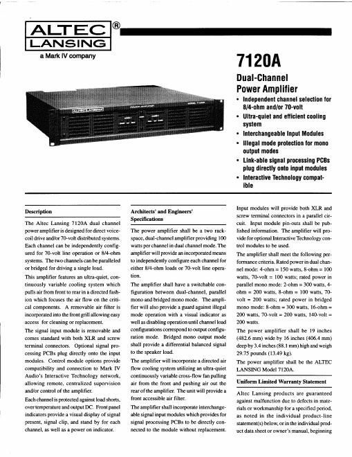
The Altec Lansing 7120A dual channel
power amplifier is designed for direct voice-
coil drive and/or 70-volt distributed systems.
Each channel can be independently config-
ured for 70-volt line operation or 8/4-ohm
systems. The two channels can be paralleled
or bridged for driving a single load.

This amplifier features an ultra-quiet, con-
tinuously variable cooling system which
pulls air from front to rear in a directed fash-
ion which focuses the air flow on the criti-
cal components. A removable air filter is
incorporatedinto the front grill allowing easy
access for cleaning or replacement.

The signal input module is removable and
comes standard with both XLR and screw
terminal connectors. Optional signal pro-
cessing PCBs plug directly onto the input
modules. Control module options provide
compatibility and connection to Mark IV
Audios Interactive Technology network,
allowing remote, centralized supervision
and/or control of the amplifier.

Each channel is protected against load shorts,
over temperature and output DC. Front panel
indicators provide a visual display of signal
present. signal clip, and stand by for each
channel, as well as a power on indicator.

Architects' and Engineers'
Specifications

The power amplifier shall be a two rack-
space, dualechanncl amplifier providing 100
watts per channel in dual channel mode. The
amplifier will provide an incorporated means
to independently configure each channel for
either 8/4-ohm loads or 70-volt line opera-
tion.

The amplifier shall have a switchable con-
figuration between dual-channel, parallel
mono and bridged mono mode. The ampli-
fier will also provide a guard against illegal
mode operation with a visual indicator as
well as disabling operation until channel load
configurations correspond to output configu-
ration mode, Bridged mono output mode
shall provide a differential balanced signal
to the speaker load.

The amplifier will incorporate a directed air
flow cooling system utilizing an ultra-quiet
continuously variable cross-flow fan pulling
air from the front and pushing air out the
rear of the amplifier. The unit will provide a
front accessible air filter.

The amplifier shall incorporate interchange-
able signal input modules which provides for
signal processing PCBs to be directly con-
nected to the module without replacement.

Input modules will provide both XLR and
screw terminal connectors in a parallel cir-
cuit. Input module pin-outs shall be pub-
lished information. The amplifier will pro-
vide for optional Interactive Technology con-
trol modules to be used.

The amplifier shall meet the following per-
formance criteria. Rated power in dual chan-
nel mode: 4-ohm = 150 watts, 8-ohm = 100
watts, 70-volt = 100 watts; rated power in
parallel mono mode: 2-ohm = 300 watts, 4-
ohm = 200 watts, 8-ohm = 100 watts, 70-
volt = 200 watts; rated power in bridged
mono mode: 8-ohm = 300 watts, 16-ohm =
200 watts, 70-volt = 200 watts. l40-volt =
200 watts.

The power amplifier shall be 19 inches
(482.6 mm) wide by 16 inches (406.4 mm)
deep by 3.4 inches (88.1 mm) high and weigh
29.75 pounds (13.49 kg).

The power amplifier shall be the ALTEC
LANSING Model 7120A.

Uniform Limited Warranty Statement

Altec Lansing products are guaranteed
against malfunction due to defects in mate-
rials or workmanship for a specified period.
as noted in the individual product-line
statement(s) below, or in the individual prod-
uct data sheet or owners manual, beginning

Page 2

7120A Dual-Channel Power Amplifier

7120A Dual-Channel Power Amplifier

with the date of original purchase. If such
malfunction occurs during the specified pe-
riod, the product will be repaired or replaced
(at our option) without charge. The product
will be returned to the customer prepaid.
Exclusions and Limitations: The Limited
Warranty does not apply to: (a) exterior fin-
ish or appearance; (it) certain specific items
described in the individual product-line
statement(s) below, or in the individual prod
uct data sheet or owners manual; (0) mal-
function resulting from use or operation of
the product other than as specified in the
product data sheet or owners manual; (d)
malfunction resulting from misuse or abuse

Input Card Pin Assignments
Pin it Name Function
1 VOUT_SFNSE_CH1 0 to S V dc. load voltage
channel one

2 vour_smse_crtz 0 to 5 V dc. load voltage

channel two

Oto 5 V dc. load current
channel one

3 tour_smse,cnr

4 rour_snnsrz_cm 0 to 5 V dc, load current

channel two
5 remnant 0 to 5 V dc, heat sink
temperature channel one
6 mgr: 0 to 5 V dc. heat sink
temperature channel two
7 Auoro_our_cut Channel one output scaled
down for 0 (Eu full scale.
Can be used for monitor-
ing or line out.
8 AUDIO_OUI'_CHZ Channel two output scaled
down forO dBu full scale.
Can be used for monitor-
ing or line out.
9 STANDBY_CH1 Control signal turns
channel one power supply
on by forcing pin to
AGND. Normally
connected to PIN 17
10 .15 V 15 V dc supply with
100 mA capacity
11 STANDBY_CH2 Control signal toms
channel two power supply
on by forcing pin to
AGND. Normally
connected to PIN 17

of the product; or (e) malfunction occurring
at any time after repairs have been made to
the product by anyone other than Mark IV
Audio Service or any of its authorized ser-
vice representatives. Obtaining Warranty
Service: To obtain warranty service, a cus-
tomer must deliver the product, prepaid, to
Mark IV Audio Service or any of its autho-
rized service representatives together with
proof of purchase of the product in the form
of a bill of sale or receipted invoice. A list
of authorized service representatives is avail-
able from Mark IV Audio Service at 10500
W. Reno Avenue. Oklahoma City. OK 73 127
(BOO-84541727 or FAX 405-577-3274). In-

PM it Name Funetlon

12 -15 v ~15 V dc supply with
100 mA capacity

13 CLIP_CH1 0 to 8 volt signal
indicating channel one clip
by going high (> 4 volts)

14 +6V 6 V dc supply with
800 mA capacity reference
only to DGND

15 cur_cnz 0 to 8 volt signal
indicating channel two clip
by going high (> 4 volts)

16 DGND DGND. reference {or

6 V dc supply (PIN l4)
l7 FAULT_CH1 Normally connected to
PIN 9. Indicates channel
one critical temp, over-
curreul. output DC or
shorted output by going
high (> 5 volts). Signal
norm is low (< 1 volt).

Referenced to AGN'D
18 norm DGND. reference for

6 V dc supply (PIN 14)
I9 FAULT_CHZ Normally connected to

PIN 9. Indicates channel
two critical temp, over-
current, output DC or
shorted output by going
high (> 5 volts). Signal
norm is low (< 1 volt).
Referenced to AGND

DGND, reference for 6
V dc supply (FIN 14)

20 DGND

cidental and Consequential Damages Ex-
cluded: Product repair or replacement and
return to the customer are the only remedies
provided to the customer. Altec Lansing shall
not be liable for any incidental or consequen-
tial damages including, without limitation.
injury to persons or property or loss of use
Some states do not allow the exclusion or
limitation of incidental or consequential
damages so the above limitation or exclu.
sion may not apply to you. Other Rights:
This warranty gives you specific legal rights,
and you may also have other rights which
vary from state to state.

Pin It Name
21 POWEILCTL

Function
shorting this pin to DGND
will power down entire
amplifier with exception of
6 V dc supply
22 AGND AGND. analog, fault and
+15-volt supply ground
reference

Unbalanced channel two
input to amplifier
referenced to AGND.
Sensitivity=0.775 V ms

23 AUDID_I'N_CH2

24 AGED AGND. analog. fault and
+15-volt supply ground
reference

25 AGND AGND. analog, fault and
+15-volt supply ground
reference

26 noun AGND. analog. fault and
+lS-volt supply ground
reference

Unbalanced channel one
input to amplifier
referenced to AGND.
Sensitivity=0.775 V ms

27 AUDIO_1N_CH1

AGND, analog, fault and
+15'volt supply ground
reference

28 norm

29 CHASSISOND Connects to chassis ground

inside amplifier
30 cmssrsono Connects to chassis ground
inside amplifier