Altec 444b 9444b sa

This is the 8 pages manual for altec 444b 9444b sa.
Read or download the pdf for free. If you want to contribute, please upload pdfs to audioservicemanuals.wetransfer.com.

Page: 1 / 8
altec 444b 9444b sa

Extracted text from altec 444b 9444b sa (Ocr-read)


Page 1

RUGGEDLY RELIABLE

DESIGNED FOR HIGH POWER/EXTENDED USE

94443 and 9444B/SA
Anniversary Series Power Amplifiers

016 Metal Output Transistors Provide a Total Device Dissipation of 4,000 watts
OPatented Output Protection Circuitry (US. Patent No. 5,029,299)

0 Superior Amplifier Cooling Provides Long Term Reliability

OUL and CSA Rated for Commercial Audio Systems

APPLICATIONS w , . .. . . ..
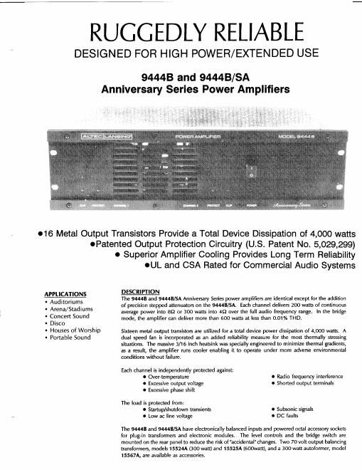
' Auditoriums The 94443 and 9444B/SA Anniversary SerIes power amplIerrs are Identical except for the addItIon

. A /St d' of precision stepped attenuators on the 9444B/SA. Each channel delivers 200 watts of continuous
rena a Iums average power into 89 or 300 watts into 49 over the full audio frequency Iange. In the bridge

' (Smelt Sound mode, the amplifier can deliver more than 600 watts at less than 0.01% THD.

' ISCO

' HOUSES 0f WOTShlP Sixteen metal output transistors are utilized for a total device power dissipation of 4,000 watts. A
' Portable Sound dual speed fan is incorporated as an added reliability measure for the most thermally stressing

situations. The massive 3/16 inch heasink was specially engineered to minimize thermal gradients,
as a result, the amplifier runs cooler enabling it to operate under more adverse environmental
conditions without failure.

Each channel is independently protected against:
0 Over-temperature 0 Radio frequency interference
0 Excessive output voltage 0 shorted output terminals
0 Excessive phase shift

The load is protected from:
O Startup/shutdown transients 0 Subsonic signals
» 0 Low ac line voltage 0 DC faults

The 94443 and 9444B/SA have electronically balanced inputs and powered octal accessory sockets
for plug-in transformers and electronic modules. The level controls and the bridge switch are
mounted on the rear panel to reduce the risk of "accidental" changes. Two 70 volt output balancing
transformers, models 15524A (300 watt) and 15525A (600watt), and a 300 watt autoformer, model
15567A, are available as accessories.

Page 2

SPECIFICATIONS FOR THE 94443 and 9444B/SA POWER AMPLIFIERS

Conditions:
1. 0 dBu = 0.775 volts rms.
2. Dual mode ratings are for each channel.
3. Both channels operating at rated output power unless
noted.
4. 120 volt ac line input voltage maintained for all tests
unless noted.

Continuous Rated Output Power:
(20 Hz - 20 kHz at less than 0.1% THD)

Dual mode, 4 Q: 300 watts/ch
Bridge mode, 8 Q: 600 watts
Dual mode, 8 Q: 200 watts/ch
Bridge mode, 16 Q: 400 watts

Continuous Rated Output Power to Subwoofer:
(20 Hz - 1 kHz at less than 0.1% THD)

Dual mode, 4 Q: 375 watts/ch
Bridge mode, 8 Q: 750 watts
Dual mode, 8 Q: 225 watts/ch
Bridge mode, 16 Q: 450 watts

Maximum Midband Output Power:
(Ref. 1 kHz, 1% THD, @120 volts ac line voltage)

Dual mode, 4 (2: >400 wam/ch
Bridge mode, 8 9: >800 watts
Dual mode, 8 9: >250 wam/ch
Bridge mode, 16 (2: >500 watts

(Ref. 1 kHz, 1% THD, @108 volts ac (10% sag»
Dual mode, 4 9: >325 watts/channel.

Bridge mode, 8 9: >650 watts.
Dual mode, 8 9: >200 watts/channel.
Bridge mode, 16 9: >400 wats.

(Ref. 1 kHz, 1% THD, @100 volts ac (17% sag»
Dual mode, 4 9: >230 watts/channel.

Bridge mode, 8 (2: >460 watts.

Dual mode, 8 9: >175 watts/channel.

Bridge mode, 16 (1: >350 watts.
Headroom (Before clip): 21 dB.

(Ref. 1 kHz, 1% THD, any mode)

frequency Response: 10 Hz - 90 kHz.
(Ref. 1 kHz, 1 watt output, +0l-3 dB)

Power Bandwidth: 20 Hz - 20 kHz.
(Ref. 1 kHz, +0/-1 dBr where 0 d8! = rated output power
in any mode)

Voltage Gain:
(Ref. 1 kHz)
Dual mode, 4 Q or 8 £2: 33 dB.
Bridge mode, 8 or 16 Q: 39 dB.

Input Sensitivity for Rated Output Power:

(Ref. 1 kHz, :0.15 dB)
Dual mode, 4 Q:
Bridge mode, 8 Q:
Dual mode, 8 9:
Bridge mode, 16 Q:

+0.1 dBu (0.78 V rms).
+1.2 dBu (0.89 V rms).

Maximum Input level: +20 dBu (775 V rms).

(Ref. 1 kHz)
Input Impedance:
(Ref. 1 kHz)
Balanced: 15 k9.
Unbalanced: 15 k9.
Polarity: Positive-going signal applied to pin

2 of XLR or (+) of barrier strip will
produce a positive-going signal at
(+) output terminal.

Phase Response:

(Any mode)
20 Hz: <+25°.
20 kHz: >-15°.
THD: <0.1% (Typically <0.01%).

(Any mode, 30 kHz measurement bandwidth)

IMD (SMPTE 4:1): <0.05% (Typically <0.01%).

(Any mode)

TIM (DIM 100): <0.05%.
(Any mode)

Rise Time: <6 psec.

(Any mode, 10% to 90%)

Slew Rate:
Dual mode, 4 or 8 £2: >30 V/usec.
Bridge mode, 8 or 16 S2: >60 V/psec.

Damping Factor:
(Dual mode, 8 S2)

20 Hz -1 kHz: >200
20 kHz: >75
Crosstalk: <75 dBr.

(Ref. 1 kHz, 0 dBr = rated output power into 8 ohms, single
channel operating)

Noise: >1 OOdB below rated output power.
(A-weighting filter, 8 9 dual mode, 50/60 Hz ac line

frequency.)

Amplifier Protection: Shorted output terminals,
Over-temperature, RF interference.

load Protection: Startup/shutdown transients, DC

faults, Subsonic signals.

Cooling:
Heatsink: Thermally equalized 3/16 inch
aluminum black anodized heatsink.
Fan: Thermostatically controlled dual

speed fan. Approximately 50 CFM
at low speed and 100 CFM at high
speed. Ball bearing fan has
minimum life rating of 50,000 hours
at 25°C ambient temperature.