Altec 436c poweramp schematic

This is the 72 pages manual for altec 436c poweramp schematic.
Read or download the pdf for free. If you want to contribute, please upload pdfs to audioservicemanuals.wetransfer.com.

Page: 1 / 72
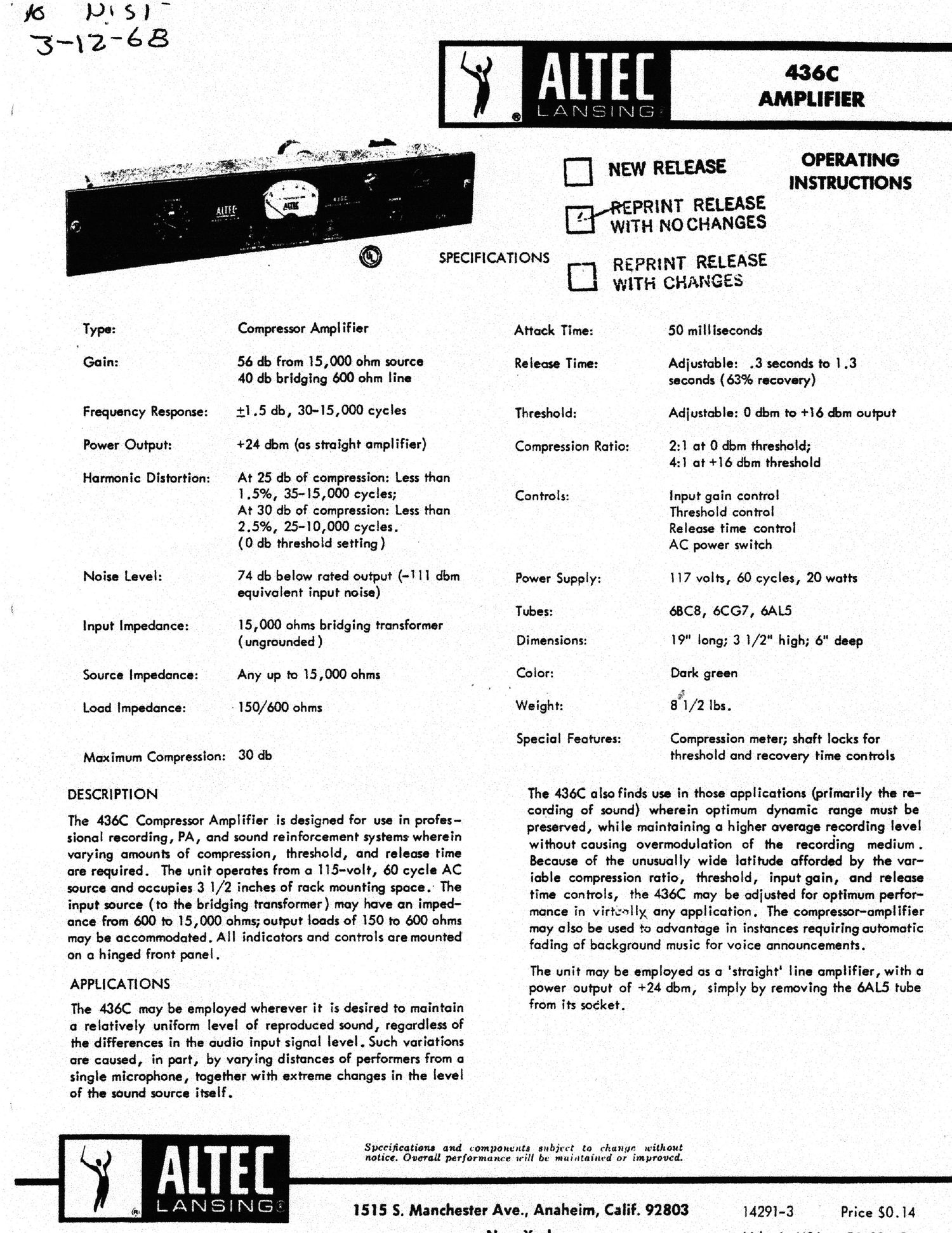
altec 436c poweramp schematic

Extracted text from altec 436c poweramp schematic (Ocr-read)


Page 2

l NSTALLATI ON

The design of the 436C compressor amplifier provides
considerable versatility of connection when used with
other components of the 15) series. The bridging input
has sufficiently high impedance that it maybe directly
connected to the output of the Alter: l566A, l567A, or
l563A line amplifiers without the use of line transformers
in these units. When the transformers are desired to pro-

vide balance and isolation from ground, a 560 ohm resis- .

tor is used across the 436C input terminals to provide
proper termination for the line transformer.

The output transformer of the 436C provides load impedan-
ces of l50 and 600 ohms and is well balanced. Because of
the transformer configuration and amplifier power capabih-
ity, it is suitable for directly feeding transmission lines or
combinations of one or more power amplifiers.

OPERATION AND USE OF CONTROLS

The 436C compressor amplifier has four controls, all
mounted on the front panel:

i: input gain control
2: Threshold control.
3: Release time control
4: AC power switch

l: lnput Gain Control:

This control is used to adiust the input level to provide the

desired average compression as indicated on the compres-
sion meter. ,

'2: Threshold Control:

The output level at which compression commences, together
with the compression ratio, is adiustable by means of this
control. in the maximum counter-clockwise position, com-
pression begins when the output is approximately zero
level. An increase in input. level of 20 db at this point
results in an output level increase of l0 &, giving a com-
pression ratio of 2:l. At maximum clockwise rotation,
compression starts when the output is approximately +i6
dbm; an increase in input level of 20 dbat this point, re-
sults in an output level increase of5 db, giving acorn-
pression ratio of 4:] (Maximum compression before distor-
tion is 22 db at this setting). The higher threshold and
flatter output characteristics may be more desirable in
applications, such as the recording of sound, where the
adiustment can be such that the maiority of the material
operates the amplifier in. the linear transfer region and the
occasional peak is compressedsufficiently (by the higher
compression ratio) to prevent .overmodulation of the re-
cording mechanism.

For background music control, on the other hand, where
the compressor function is to equalize differences in re-
cording level and pragrmn dynamics, the zero level
threshold and 2:l ratio are more desirable. In this appli-
cation, "average" level material is used to set the com-
pressor for to to 15* & of compression, and expansion or
compression results for material of lower or higher level
than the standard "average. input-output characteristics
are shown in more detail on the accompanying "transfer
graph" for three settings of the threshold control.

3: Release Time Control

The time interval required to restore full gain following a
condition of compression is actionable in. the range of .3

OUTPUT 08M

iNPUT 08M BRlDGlNG 600' OHM LINE
(APPROXtMATE GAIN CONTROL MAX )

seconds to l .3 seconds by means of this control. in appli-
cations such as sound recording, where only an occasional

peak actuates the compressor, the faster release times will
be found desirable.

For public-address usage, where the compressor is utilized
as an averaging device to compensate for variances in
microphone and speech levels, the longer release time

will be found desirable.

4: AC Power Switch:

This control operates the power switch (Altec 121804),
turning the compressor amplifier on and off , as indicated
by the front panel pilot light.

CONTROL LOCKS

Both the threshold and __ release time controls are of the
screwdriver adiustment type and are mounted flush with
the front panel. A l/2" open and wrench is required for
loosening and tightening the shaft locks before and after
adiustment. (The front panel must be dropped to gain
access to the locks.)

COMPRESSiON METER

it is usually desirable to have the compression meter visi-
ble from the operating position. When conditions dictate a
remote location for the compressor amplifier, an Altec
6049 meter is connected in parallel with the front panel
by means of a pair of wires extended to the console loca-
tion.

SERVICING

All circuit components are easily reached by opening the
hinged front panel of the unit. Normal servicing may be
done with a volMeter; all pertinent information is shown
on the accompanying schematic.