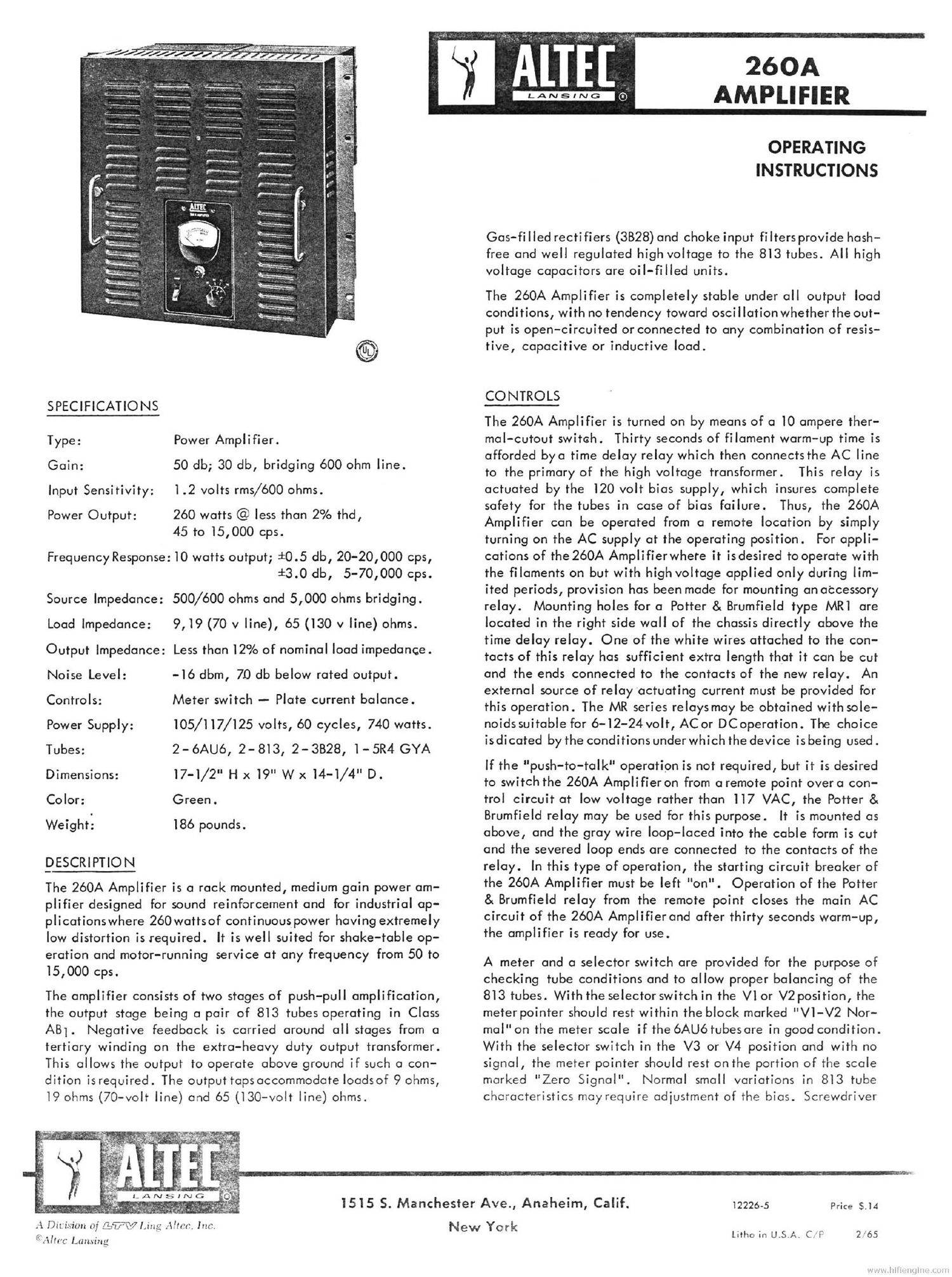
Altec 260a poweramp service manual
This is the 6 pages manual for altec 260a poweramp service manual.
Read or download the pdf for free. If you want to contribute, please upload pdfs to audioservicemanuals.wetransfer.com.
Extracted text from altec 260a poweramp service manual (Ocr-read)
Page 1
73.". ~-
\ .
_ .
fa"
.' )1
ii",
-.:'
. .
'
y.)
,.
{1
. I.
2
"re-
5'?
"I
~ 1!
~ 5'
TL
1
t' g .
3;
. .9.
as
.L-
>3?
1 .
. It:
pr}.
I . i '. . . . ,. I ~.' a t... .ul. ' 2 *.
Ix r: . «- -.' ,,_' r'. I . l 'f" .
H. .. . ,,. m. . , t - .s N ,
, _ _ . .. . H . n \. ..- nu}. -...
'\
9'? "5 48mm x :J'..: I??? 7'77: "
". twig-T ' 1.9. r.-
a"...a .':-s 23 .I
:~)
.hzsr
SPECIFICATIONS
Type: Power Amplifier.
Gain: 50 db; 30 db, bridging 600 ohm line.
I .2 volts rms/600 ohms.
260 watts @ less than 2% thd,
45 to I5,000 cps.
Frequency Response: IO watts output; i0.5 db, 20-20,000 cps,
i3.0 db, 5-70,000 cps.
Source Impedance: 500/600 ohms and 5,000 ohms bridging.
9, I9 (70 v line), 65 (I30 v line) ohms.
Input Sensitivity:
Power Output:
Load Impedance:
Output Impedance: Less than I2% of nominal load impedance .
Noise Level: -I6 dbm, 70 db below rated output.
Meter switch - Plate current balance.
Power Supply: IOS/I I7/I25 volts, 60 cycles, 740 watts.
Tubes: 2 - 6AU6, 2 - 8l 3, 2 - 3828, I - 5R4 GYA
I7-I/2" H x I9" W x I4-I/4" D.
Controls:
Dimensions:
Color: Green .
Weight: I86 pounds.
[DESCRIPTION
The 260A Amplifier is a rack mounted, medium gain power am-
plifier designed for sound reinforcement and for industrial ap-
plicationswhere 260 wattsof continuous power having extremely
low distortion is required. It is well suited for shake-table op-
eration and motor-running service at any frequency from 50 to
I5,000 cps.
The amplifier consists of two stages of push-pull amplification,
the output stage being a pair of 8I3 tubes operating in Class
A8}. Negative feedback is carried around all stages from a
tertiary winding on the extra-heavy duty output transformer.
This allows the output to operate above ground if such a con-
dition is required. The outputtaps accommodate loadsof 9 ohms,
I9 ohms (70-volt line) and 65 (I30-volt line) ohms.
vv .
. | .' . . - - .... q
_ . v- 4 ._ | y L; 1 g
. - . >.7 Q .r I'lf .. .y 7 , _ II p
a .. ~,~ ' v J . ( i 10.. .5 if; " ". ._ "~ l... "'
ISIS S. Manchester Ave., Anaheim, Calif. 12226-5
260A
AMPLIFIER
OPERATING
INSTRUCTIONS
Gas-filled rectifiers (3828) and choke input filters provide hash-
free and well regulated high voltage to the 8I3 tubes. All high
voltage capacitors are oil-filled units.
The 260A Amplifier is completely stable under all output load
conditions, with no tendency toward oscillation whether the out-
put is open-circuited or connected to any combination of resis-
tive, capacitive or inductive load.
CONTROLS
The 260A Amplifier is turned on by means of 0 I0 ampere ther-
mal-cutout switch. Thirty seconds of filament warm-up time is
afforded bya time delay relay which then connects the AC line
to the primary of the high voltage transformer. This relay is
actuated by the I20 volt bias supply, which insures complete
safety for the tubes in case of bias failure. Thus, the 260A
Amplifier can be operated from a remote location by simply
turning on the AC supply at the operating position. For appli-
cations of the 260A Amplifierwhere it is desired to operate with
the filaments on but with high voltage applied only during lim-
ited periods, provision has been made for mounting an atcessory
relay. Mounting holes for a Potter & Brumfield type MRI are
located in the right side wall of the chassis directly above the
time delay relay. One of the white wires attached to the con-
tacts of this relay has sufficient extra length that it can be cut
and the ends connected to the contacts of the new relay. An
external source of relay actuating current must be provided for
this operation. The MR series relays may be obtained with sole-
noids suitable for 6-I2-24 volt, AC or DC operation. The choice
isdicated by the conditions under which the device is being used.
If the "push-to-talk operation is not required, but it is desired
to switch the 260A Amplifier on from a remote point overa con-
trol circuit at low voltage rather than II7 VAC, the Potter &
Brumfield relay may be used for this purpose. It is mounted as
above, and the gray wire loop-laced into the cable form is cut
and the severed loop ends are connected to the contacts of the
relay. In this type of operation, the starting circuit breaker of
the 260A Amplifier must be left "on" . Operation of the Potter
8. Brumfield relay from the remote point closes the main AC
circuit of the 260A Amplifier and after thirty seconds warm-up,
the amplifier is ready for use.
A meter and a selector switch are provided for the purpose of
checking tube conditions and to allow proper balancing of the
813 tubes. With the selector switch in the VI or V2 position, the
meter pointer should rest within the block marked "VI-V2 Nor-
mal" on the meter scale if the 6AU6 tubesare in good condition.
With the selector switch in the V3 or V4 position and with no
signal, the meter pointer should rest on the portion of the scale
marked "Zero Signal" . Normal small variations in 8I3 tube
characteristics may require adjustment of the bias. Screwdriver
Price $.I4
New York
A Division of £3377??? Ling .Itfrr. Inc.
f.» . . Litho in U.S.A. CL? 265
- :tfllC Lam-mg
Page 2
adiustment of the bias potentiometers is provided through holes
located in the meter panel on either side of the trade-mark.
With signalapplied and the tubesdelivering powerinto the load,
the meter pointer will swing over the portion of the scale marked
"V3-4 OPERATING RANGE". When delivering full power, the
pointer will hover over the right hand end of this portion of the
scale. Intermediate Ievelswill cause the meter to read between
the quiescent and full power limits. Rapid variations in speech
and music will cause deflections over this range.
POWER co NNgcllgNs
The two power transformers of the 260A Amplifier have primary
taps for I05, II7, and I25 volts. Thetap which most nearly
approximates the average line voltage should be used. It is
desirable that the wire from the AC line be of such size that no
appreciable voltage drop will occur at a current of 8 amperes,
which is the drain on the line when the amplifier is delivering
full power. '
OUTPUT CONNECTIONS
4-?
For sound reinforcement, loudspeakers with voice coil imped-
ances from8 to 16 ohms may be directly connected to the 9 ohm
output tap .
For multiple loudspeaker operation, the 70-volt distribution line
should be used. At this top, the amplifier delivers rated audio
output at 70 volts. Using loudspeakers equipped with 70-volt
line transformers, it is only necessary to connect the chosen
wattage tap on the transformer to the speaker distribution line.
The amplifier will operate correctly providing the sum of the
power drawn by all the speakers does not exceed the power rat-
ing of the amplifier. Total power can be divided among speakers
as desired. Due to the excellent output voltage regulation of
the 260A. speakers or groupsof speakers can be switched on and
off without the necessity of providing dummy loads, and as
speakers are connected or disconnected, there will be no ap-
parent change in volume level.
When losses in a 70-volt distribution system tend to be large,
the use of 0 I30 volt line may offer very attractive economies.
Loudspeaker 70-volt line transformers may be used on lBO-volt
line by connecting the line to a top rated at one quarter of the
desired power, For example, if the speaker is to draw one watt,
connect it to the proper impedance terminal of the transformer
and connect the I30-volt line to a 1/4 watt terminal.
The l30-voltoutput tap also providesa suitable source of power
to operate motors and other electrical apparatus normally sup-
plied from I17 VAC lines. In this service, the amplifier is cap-
able of continuously delivering 260 volt-amperes to the load at
any frequency from 50 cycles to l5,000 cycles.
If the full power capabilities of the amplifier are to be utilized
when the load is a motor or other induction apparatus having a
low power factor, it is essential that corrective capacitors be
added to the circuit.
INPUT CONNECTong
As shipped, the input transformer is connected for operation from
a 500 ohm line. Aline level of +4.5 dbm (l .2 volts)will drive
the 260A Amplifier to full power. Where higher levels are a-
vailable, a bridging connection will reduce the gain by 20 db.
If required, line impedancesof 30/50, I25/I50, or 250/300 can
be matched by strapping the input transformer terminals in ac-
cordance with the chart illustrated on the schematic.
In some instances, the 260A Amplifier may replace a power am-
plifier such as the Altec 287W in an existing system where an
amplifier of moderate power is used as a driver. In this case, it
is necessary to terminate the driver amplifier witha load resistor
to match the rated output and impedance of the driver. The
5,000 ohm input connection on the 260A Amplifier should be
connected across this load resistor.
MOUNTING
The 260A Amplifier isdesigned for mounting in astandard relay
rack. Wall mounting can be accomplished by the use of the
I2I56 Assembly. Assemble the two side members to the two
channel iron rails as indicated in the exploded view of Figure I.
Attach this assembly to the wall by means of toggle bolts or log
screws through the holes in the rails. Mount the 260A between
the side members by means of 12-24 screws in the tapped holes
located inthe front edgesof the side members. Attach the nec-
essary conduits in the knockouts provided in the side members.
Wire the amplifier through the holes which line up with the
knockouts in the chassis. Install the side covers to conceal all
wiring. Installation of these covers also conceals the mounting
screws of the amplifier. When assembled completely, this unit
is extremely rigid.
SAFETY PRECAUTIONS
All practical safety precautions have been incorporated in the
design of the 260A Amplifier, including an interlock switch
which interrupts the AC line to the high voltage transformer when
the cover is removed. A potential of I,800 voltsoccurs at sev-
eral pointsin this amplifier. Therefore, do not defeat the inter-
lock switch, and do not attempt tube replacement or service
work with the power turned on.
The high voltage condensers are equipped with bIeeders which
will normally dissipate any charge within a few seconds after
the power is turned off. However, an unsuspected open bleeder
could leave a dangerous charge on a condenser, and it is good
practice to discharge all filter condensers with a short circuit
before any work is done.
In view of the above, trouble shooting on the amplifier should
be done by means of resistance and continuity checks, with the
power turned off. The schematic diagram shows all pertinent
resistance values to aid in servicing the amplifier.
I :-. J
NOTE!
Modification of wiring or components within the amplifier will
void the Underwriter Laboratories listing and make equipment
subject to local inspection at time of installation.