Altec 1432a manual

This is the 19 pages manual for altec 1432a manual.
Read or download the pdf for free. If you want to contribute, please upload pdfs to audioservicemanuals.wetransfer.com.

Page: 1 / 19
altec 1432a manual

Extracted text from altec 1432a manual (Ocr-read)


Page 1

ALTEC

1432A
Variable Q Active Filter

Stereo 31 Band 1/3 Octave Equalizer

KEY FEATURES

fir Variable Q filter set

* 31 bands of boost and cut

A' Select between 6 dB or 12 dB
of boost and cut

KEY SYSTEM SPECIFICATIONS

20, 25, 32, 40, 50, 63, 80,
100, 125, 160, 200, 250, 315,
400, 500, 630, 800, 1k,
1.25k, 1.6k, 2k, 2.5k, 3.]5k,
4k, 5k, 6.3K, 8k, 10k, 12.5k,
16k Hz, 20k Hz

Center Frequencies:

Maximum Boost/Cut: 112 dB
Operating Gain: 0 dB
Low-Cut Filter
Comer Frequency: 43 Hz
Frequency Response
at Unity Gain: 20 Hz ~ 20 kHz, 2 1 dB

(High-Pass Filter Disengaged)

Total Harmonic Distortion

at Unity Gain: < 0.01%
(20 Hz - 20 kHz, 0 dBu Output)

Noise at Unity Gain: < -85 dBu
(20 Hz - 20 kHz)
Maximum Input Level
at Unity Gain: + 20 dBu (7.75 Vrms)
Maximum Output Level: + 20 dBu (7.75 Vrms)
DESCRIPTION

The Altec Lansing 1432A Dual Channel Stereo
Val-Octave Graphic Equalizer is a boost and cut
equalizer whose primary use is for tuning the
overall frequency response of a sound reinforce-
ment system, both to increase gain-be fore-feedback
and to compensate for the deficiencies in the
acoustic environment and the sound system.

The active Q variable filter set utilized in the
1432A allows effective equalization with few pro-
blematic side effects. As Figure 2 illustrates, the
filter characteristics vary with the amount of boost
or cut used. At low control settings, the filter Q is
very wide. As the control is boosted or cut, the filter

Q narrows so that there is minimum interaction
between adjacent frequency bands. The filter
response is designed to affect a I/:4-octave range.

Each of the 31 I/:s-octave filters provide 12 dB of
boost or cut at [$0 frequencies 20 through 20,000
Hz. The faders have apositive detent in the center,
fiat-response position. The gain control also has a
center detent at unity gain.

A low-cut filter switch. with a 43 Hz comer
frequency and 18 dB per octave slope, is located
on the front panel. A range select switch allows
selection of either 6 dB or 12 dB of boost or cut.

Page 2

Input:

W:
Impedance:
Non-rial level:
Output:
Type:
Impedance:

load impedance:

Peak Indicator:

Available Gain:

High-Pass Filter:

Controls:

1432A Specifications (cont'd)

(Ref. 0 dBv = 0.775 Vrms)
Electronically balanced

44 k0 balanced

22 k0 unbalanced

0 dBv (0.775 Vrms)

(Ref. 0 dBm = 0.775 Vrms
across 600 Q)
Electronically balanced
120 0 balanced

60 O unbalanced

600 .0. or higher

Red LED + 14 dBu (6 dB
before clipping)

:GdBortIZdB

Switch selectable with
cutoff below 43 Hz and a
slope of 18 dB per octave.

o 3] center detent slide
controls at 'A-octave cen-
ter frequencies from 20
Hz to 20 kHz, selectable
: 6 dB or t 12 dB
boost/cut.

o LEVEL control with
center detent

O LO-CUT select switch

ORANGEifidBor: 12
dB select switch

Connectors:
Input:

Output:

AC Power:

Operating Temperature
Range:

Dimensions:

Height:

Width:

Depth:

Net Weight:

Enclosure:

Accessories:

alter Lansing
mow

MPH!!!) vs I'l'lEt'lOlz)

DJ. APR 9213::11

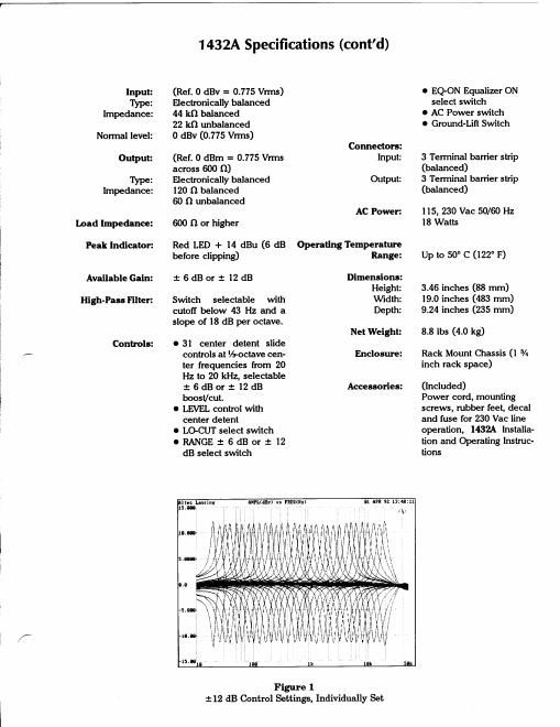
Figure 1
:12 dB Control Settings, Individually Set

O EQ-ON Equalizer ON
select switch

0 AC Power switch

0 Ground-Lift Switch

3 Terminal barrier strip
(balanced)
3 Terminal barrier strip
(balanced)

5, 230 Vac 50/60 Hz
18 Watts

Up to 50° C (122" F)

3.46 inches (88 mm)
19.0 inches (483 mm)
9.24 inches (235 mm)

8.8 lbs (4.0 kg)

Rack Mount Chassis (l 3/4
inch rack space)

(included)

Power cord, mounting
screws, rubber feet, decal
and fuse for 230 Vac line
operation, 1432A installa-
tion and Operating Instruc-
tions