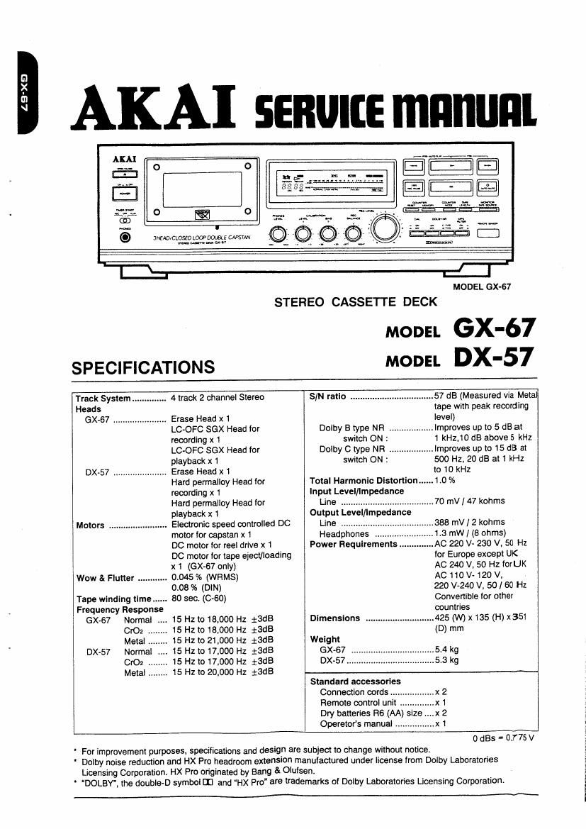
Akai GX 67 Service Manual
This is the 35 pages manual for Akai GX 67 Service Manual.
Read or download the pdf for free. If you want to contribute, please upload pdfs to audioservicemanuals.wetransfer.com.
Extracted text from Akai GX 67 Service Manual (Ocr-read)
Page 1
LB'XS
KAI senurre mnnunl
til - i-
EEEE
MODEL (EX-67
STEREO CASSETTE DECK
SPECIFICATIONS
MODEL GX-67
MODEL DX-57
Track System .............. 4 track 2 channel Stereo SIN ratio .................................. 57 dB (Measured via Meta
Heads tape with peak recording
GX-67 ...................... Erase Head x 1 level)
LC~OFC SGX Head for Dolby B type NR .................. Improves up to 5 dB at
recording x 1 switch ON : 1 kHz,10 dB above 5 kHz
LC-OFC SGX Head for Dolby C type NR .................. Improves up to 15 dB at
playback x 1 switch ON : 500 Hz, 20 dB at 1 kHz
DX-57 Erase Head x1 to 10 kHz
Hard permalloy Head for Total Harmonic Distortion ...... 1.0 %
recording x 1 input Level/Impedance
Hard permalloy Head for Line ...................................... 70 mV / 47 kohms
playback x 1 Output Level/Impedance
Motors ........................ Electronic speed controlled DC Line .............. 388 mV l 2 kohms
motor (or capstan x 1 Headphones 1.3 mW I (8 ohms)
DC motor for reel drive x 1 Power Requirements ...AC 220 V- 230 V, 50 Hz
DC motor for tape eject/loading for Europe except UK
x 1 (GX-67 only) AC 240 V, 50 Hz forUK
Wow 8t Flutter ............ 0.045 % (WRMS) AC 110 V- 120 V,
0.08 % (DlN) 220 V240 v, 50/60 Hz
Tape winding tlme ...... 80 sec. (0-60) Convertible for other
Frequency Response countries
GX-67 Normal 15 Hz to 18,000 Hz 13:18 Dimensions ............................ 425 (W) x 135 (H) X351
CrOz ........ 15 Hzto13,ooo Hz $3.18 (D) mm
Metal ........ 15 Hz to 21,000 Hz i3dB Weight
DX-57 Normal 15 Hz to 17,000 Hz iSdB GX-67 ..
CrOz .. 15 Hz to 17,000 Hz iSdB DX-57....
Metal ........ 15 Hz to 20,000 Hz 13dB
Standard accessories
Connection oords
Remote control unit
Dry batteries R6 (AA) size
Operator's manual ................ x 1
0 (185 = 0.775 V
For improvement purposes, specifications and design are subject to change without notice.
Dolby noise reduction and HX Pro headroom extension manufactured under license from Dolby Laboratories
Licensing Corporation. HX Pro originated by Bang & Olufsen.
' DOLBY. the double-D symbol [I] and HX Pro" are trademarks or Dolby Laboratories Licensing Corporation.
Page 2
* SAFETY INSTRUCTIONS
PRECAUTIONS DURING SERVICING
1. Parts identified by the A (*) symbol are critical for
safety. Replace only with parts number specified.
2. In addition to safety, other parts and assemblies are
specified for conformance with such regulations as those
applying to spurious radiation.
These must also be replaced only with specified re-
placements.
Examples: RF converters, tuner units. antenna selector
switches, RF cables, noise blocking capacitors, noise
blocking filters, etc.
3. Use specified internal wiring. Note especially:
1) Wires covered with PVC tubing
2) Double insulated wires
3) High voltage leads
4. Use specified insulating materials for hazardous live
pans. Note especially:
1) insulation Tape
2) PVC tubing
3) Spacers (insulating barriers)
4) insulation sheets for transistors
5) Plastic screws for fixing microswitch (especially in
turntable)
5. When replacing AC primary side components (trans-
formers, power cords, noise blocking capacitors, etc),
wrap ends of wires securely about the terminals before
soldering.
entail
6. Observe that wires do not contact heat producing pans
(heatsinks, oxide metal film resistors, fusible resistors,
etc).
* INFORMATION
7. Check that replaced wires do not contact sharp edged
or pointed parts.
8. Also check areas surrounding repaired locations.
9. Use care that foreign objects (screws, solder droplets,
etc.) do not remain inside the set.
SAFETY CHECK AFTER SERVICING
After servicing, make measurements of leakage-current or
resistance in order to determine that exposed parts are
acceptably insulated from the supply circuit.
The leakage-current measurement should be done be-
tween acoessible metal pans (such as chassis, ground
terminal, microphone jacks, signal input/output connec-
tors, etc.) and the earth ground through a resister of 1500
ohms paralleled with a 0.15 pF capacitor. under the units
normal working conditions. The leakage-current should be
less than 0.5 mA rms AC.
The resistance measurement should be done between
accessible exposed metal parts and power cord plug prongs
with the power switch (it included) ON". The resistance
should be more than 2.2 Mohms.
MAKE YOUR CONTRIBUTION TO PRO-
TECT THE ENVIRONMENT
Used batteries with the 180 symbol for recy-
cling as well as accumulators (rechargeable 053/
batteries), mini-batteries (cells) and starter %
batteriesshould not be thrown into the gar-
bage can.
Please leave them at an appropriate depot. All other house-
hold batteries can be thrown out with the household waste.
SYMBOLS FOR PRIMARY DESTINATION
Primary destinations of units are indicated with the follow-
ing alphabet.
Symbols Primary Destinations
UK
E Europe (except UK)
Australia
Germany
in Universal Area
Custom version
SERVICE MANUAL
VOLTAGE CONVERSION ( Model only)
Before connecting the power cord, set the VOLTAGE
SELECTOR located on the rear panel with a flat type
screwdriver so that the correct voltage for your area is
indicated.
VOLTAGE
SELECTOR
i
,
Page 9
IV.MECHANICAL ADJUSTMENT
4-1.CONFIRMATION 0F PINCH ROLLER
PRESSURE
1) Set the unit in the PLAY mode without a cassette tape
loaded.
2) Push the TAKE UP PINCH ROLLER arm down 1 or 2
mm from the capstan with a spring gauge.
Release the pressure of the spring gauge little by little
and read the scale at the moment when the TAKE UP
PINCH ROLLER touches to the capstan and starts rota-
tion.
Also confirm the SUPPLY PINCH ROLLER pressure
with the same procedure as above.
Specified pinch roller pressure:
TAKE UP PINCH ROLLER : 320 3; 50 grams
SUPPLY PINCH ROLLER : 200 i 40 grams
0 If either of the PINCH ROLLERs pressure is not satis-
factory, replace it.
SPRING GAUGE
(TAKE UP)
PINCH ROLLER (A)
(SUPPLY)
PINCH ROLLERIBI
PINCH ROLLER (3) SPRING PINCH ROLLEFHTI SPRING
Fig. 4-1
4-2.CONF|RMATION OF WINDING
TORQUE IN EACH MODE
1) Insert the CASSETTE TORQUE METER (Al-751179).
2) Read the TORQUE METER in each mode. For fast
tonNard and rewind, read at the end of the tape when
the tape has stopped running.
PLAY mode
TAKE UP TORQUE : 35 to 55 grams
BACK TENSION : 5 to 10 grams
FF and RWD mode : 70 to 160 grams
CASSETTE TORQUE MEYER
IAJ75I I79)
SERVICE MANUAL
4-3.TAPE SPEED ADJUSTMENT
1) Connect a frequency counter to the LINE OUT and play
back a 3150 Hz test tape (AT-751263).
2) Insert a small flat screw driver into a hole on the capstan
motor and adjust the tape speed control VR so that the
reading on the frequency counter is 3150 110 Hz.
0 0 CAPSTAN MOTOR
TAPE SPEED
ADJUSTMENT HOLE
Fig. 4-3
4-4.HOW TO REMOVE A JAMMED
CASSETTE TAPE
if a damaged tape or defective tape drive mechanism
causes a cassette tape to be caught by the capstan,
remove the tape from the mechanism block using the
following procedure.
1) Place your index finger under the mechanism block and
turn the capstan wheel (take up side) counterclockwise
until the jammed tape loosens.
2) Press the EJECT button. (OX-57 only)
3) Disconnect the LOADING MOTORS P110 connector
from the PRE AMP PCB. (GX-67 only)
4) Connect a 4.5 V battery onto the LOADING MOTOR
and eject the tape. (GX-67 only)
CAPSTAN wheel
= PRE AMP PCB
AVIIII
MECHA BLOCK
FRONT PANEL
Fig. 4-4
. ! i; E LOADlNGMDTOR
MECHABLOCK Tl' /
4 .l /
DISCDlneEI the PVC-
ofl FRE AMP PCB
4
_ DC 4.5V
- BATTERY
IGX»67 only]
Fig. 45