Akai GX 630 DSS Owners Manual

This is the 24 pages manual for Akai GX 630 DSS Owners Manual.
Read or download the pdf for free. If you want to contribute, please upload pdfs to audioservicemanuals.wetransfer.com.

Page: 1 / 24
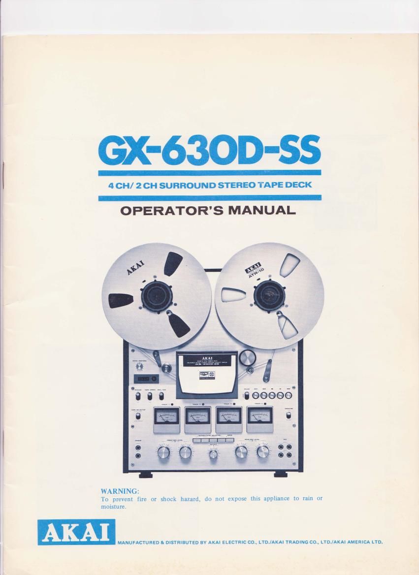
Akai GX 630 DSS Owners Manual

Extracted text from Akai GX 630 DSS Owners Manual (Ocr-read)


Page 1

X-63OD-SS

4 CH/ 2 CH SURROUND STEREO TAPE DECK

OPERATOR'S MANUAL

WARNING:
To prevent fire or shock hazard do not expose this appliance to rain or
moisture.

- MANUFACTURED & DISTRIBUTED BY AKAI ELECTRIC CO., LYDI/AKAI TRADING CO, LTD/AKIN AMERICA LTD.

Page 5

10.
ll.

** [2.

l3.

" 14.

[5.

16.

I7.

* 18.

19.

to 2m

21.

It 22'

23.

24.

25 .
26.

BUILT~IN REEL RETAINER (left)

To lock reel firmly into place, pull tip or retainer outward and

turn to left or right.

SUPPLY REEL TABLE

HEAD COVER

Houses (from left) Rear-CH Erase Head, Front-CH Erase Head,

4 TR 2»CH/4VCH GX Recording Head, and 4 TR 2-CH/4-CH

GX Playback HBad.

INDIVIDUAL TRACK RECORDING INDICATOR LAMPS

Lights to indicate recording mode of each respective track.

IMPEDANCE ROLLER

TAPE TENSION LEVER

Provides ideal tape tension.

PITCH CONTROL

Refer to PITCH CONTROL.

* This Pitch Control must be kept at 12 oclock position
except during pitch control playback.

INDEX COUNTER AND RESET BUTTON

TAPE SPEED SELECTOR

Set to 7-1/2 or 3-3/4 ips according to desired speed.

POWER SWITCH

REEL SIZE SELECTOR

Set to 10 in when using 10-1/2" reels and to 7 in when

using 7"or S" reels.

TRACK 3 VU METER

Indicates Track 3 recording and playback levels.

TAPE SELECTOR SWITCH

WIDE RANGE: Set to this position when using Wide Range

Tape.

LOW NOISE: Set to this position when using Low Noise Tape.

* Akai LN-150-7 or Scotch #111 LOW Noise Tape is
considered standard for this machine. The use of regular
tape is not recommended.

" Set to Wide Range position only when using special wide
range tape of a grade higher than low noise.

TRACK I VU METER

Indicates Track 1 recording and playback levels.

TRACK l, 2. 3, & 4 QUADRA-SYNC SELECTOR SWITCHES

Refer to QUADRAVSYNC RECORDING. page 10.

These switches must be kept at OFF (out position) except
during Quadrarsync recording.

FRONT CHANNEL HEADPHONE JACK

For front channel monitoring or headphone listening.

REAR CHANNEL HEADPHONE JACK

For rear channel monitoring or headphone listening. These

jacks accomodate any low impedance 8 ohm type stereo

headphones.

TRACK I MIC INPUT LEVEL CONTROL

Controls Track 1 microphone input volume. Adjust while

observing Track 1 VU Meter.

TRACK I LINE INPUT LEVEL CONTROL

Controls Track 1 line input volume. Adjust while observing

Track 1 VU Meter.

TRACK 3 MIC INPUT LEVEL CONTROL

Controls Track 3 microphone input volume. Adjust while

observing Track 3 VU Meter.

TRACK 3 LINE INPUT LEVEL CONTROL

Controls Track 3 line input volume. Adjust while observing

Track 3 VU Meter.

FRONT CHANNEL OUTPUT LEVEL CONTROL

Adjusts front channel output volume during playback.

REAR CHANNEL OUTPUT LEVEL CONTROL

Adjusts rear channel output volume during playback.

BUILT-IN REEL RETAINER (right)

To lock reel firmly into place, pull tip of retainer outward and

turn to left or right.

TAKE~UP REEL TABLE

PAUSE SWITCH

Depress to temporarily suspend tape travel during recording or

27.

28.
29.
30.

31.

32.
33.

34.

35.

36.

37.

38.
** 39.
w 40
42.
43.
44.
45.
46.

47.

48.

49.
50.
51.
52.
53.

54.
u 55.
" 56'.
** 57.
** 58.

playback. Especially convenient for editing tape. Simply

depress when a certain portion of the program is not desired.

* Pause Control does not function during Fast Forward or
Rewind Mode.

RECORDING (REC) BUTTON

Depress this Button and the Play > Button simultaneously to

effect recording mode.

REWIND « BUTTON

Rewinds tape at high speed.

PINCH WHEEL

Presses against capstan to transport tape.

CAPSTAN

AUTOMATIC STOP/TAPE TENSION LEVER

STOP - BUTTON

PLAY V BUTTON

Advances tape for recording or playback mode.

FAST FORWARD » BUTTON

Advances tape at high speed.

TRACK 2 VU METER

Indicates Track 2 recording and playback levels.

TAPE MONITOR SWITCH

Set to SOURCE position to monitor source and to TAPE

position for playback or private headphone listening.

TRACK 4 VU METER

Indicates Track 4 recording and playback levels.

4CH/ZCH MODE SELECTOR SWITCH

Set to OUT position for 4-CH mode, and to IN position for

2-CI-I mode. (only FRONT channel functions at 2-CH mode)

TRACK I MICROPHONE JACK

TRACK 3 MICROPHONE JACK

TRACK 4 MICROPHONE JACK

TRACK 2 MICROPHONE JACK

TRACK 4 LINE INPUT LEVEL CONTROL

Controls Track 4 line input volume. Adjust while observing

Track 4 VU Meter.

TRACK 4 MIC INPUT LEVEL CONTROL

Controls Track 4 microphone input volume. Adjust while

observing Track 4 VU Meter.

TRACK 2 LINE INPUT LEVEL CONTROL

Controls Track 2 line input volume. Adjust while observing

Track 2 VU Meter.

TRACK 2 MIC INPUT LEVEL CONTROL

Controls Track 2 microphone input volume. Adjust while
observing Track 2 VU Meter.

CYCLE CHANGE SWITCH (CEE. CSA, UL and LA models
not equipped with this facility)

Set to 50 Hz or 60 Hz position according to area power source.

REMOTE CONTROL JACK

Remote control of all operating functions can be accomplished

with optional accessory Remote Control Unit R017.

* Absentee recording can also be accomplished by using
Remote Control Unit RC-I7 together with a timer. (See
ABSENTEE RECORDING procedure)

TRACK 2 LINE INPUT JACK
TRACK 2 LINE OUTPUT JACK
TRACK 4 LINE OUTPUT JACK
TRACK 4 LINE INPUT JACK

UNIVERSAL VOLTAGE SELECTOR (CEE,CSA,UL and LA
models not equipped with this facility)

For Voltage change, refer to VOLTAGE AND CYCLE CON-
VERSION procedure.

A.C. CORD

TRACK 1 LINE INPUT JACK
TRACK 1 LINE OUTPUT JACK
TRACK 3 LINE OUTPUT JACK
TRACK 3 LINE INPUT JACK

During Z£hannel operation, only the Front Channel Controls etc. function. (Track 1 Inputs, Outputs, Indicators and Controls function
as the left channel, and Track 3 Inputs, Outputs, Indicators and Controls function as the right channel.)

Page 14

TAPE SPLICING AND EDITING

Cut the tape diagonally with an overlap so that the ends are
lined up. Cutting tape on the diagonal eliminates detection
of the splice in recording. Cover aligned ends with splicing
tape, exerting pressure to secure ends evenly. Trim off
excess splicing tape. Cutting into the tape very slightly will
eliminate the possibility of a sticky splice. Splicing using
scissors requires skillful work. For smooth and easy
splicing, Akai Tape Splicer AS-3 is highly recommended.

-\INTEN:\N('I:

HEAD BLOCK CLEANING

Heads

The GX (glass and crystal) Heads do not require a great deal
of cleaning. However, if old tapes or tapes which have been
spliced are used, GX head cleaning is also recommended,
Clean recording, playback, and erase heads with a cotton
swab stick which has been dipped in Akai Cleaning fluid
from Head Cleaning Kit HC-SOO.

Pinch wheel and capstan

If foreign matter is allowed to accumulate on the pinch
wheel and capstan, these particles will come off on the tape
causing deterioration of sound quality. Oil adhering to the
capstan also causes irregularity in tape transport. Therefore,
it is also recommended that these parts be wiped clean
periodically. Use Akai cleaning fluid or alcohol.

Do not use chemicals such as chlorothane, etc, for head block
cleaning as the rubber parts will deteriorate.

HEAD DEMAGNETIZING

Prolonged use of the machine will gradually build up
residual magnetism on the heads. The effect of magnetiza-
tion is that it causes a considerable drop in high frequency
response and introduces noise into your recordings. It is
therefore, recommended that head demagnetizing be per-
formed periodically. This can be accomplished with a bulk
head demagnetizer by bringing the prongs of the demagne»
tizer close to the heads and making several small circular
motions over all head surface areas as well as the head
housing,

" Turn off the power of the unit prior to demagnetizing the heads.

Do not use magnetized tools in the vicinity of the heads and VU
Meters.

Do not bring the magnetizer close to the VU Meters.