Akai AC 420 Service Manual

This is the 53 pages manual for Akai AC 420 Service Manual.
Read or download the pdf for free. If you want to contribute, please upload pdfs to audioservicemanuals.wetransfer.com.

Page: 1 / 53
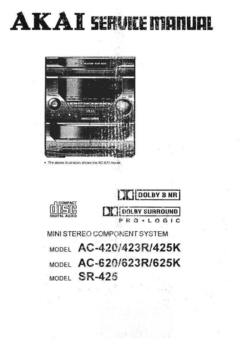
Akai AC 420 Service Manual

Extracted text from Akai AC 420 Service Manual (Ocr-read)


Page 2

CONTENTS

SAFETY INSTRUCTIONS .......

INFORMATIONS
SPECIFICATIONS .........
CONTROLS ..................
I. DISASSEMBLY .....

ll. PRINCIPAL PARTS LOCATION IIIII
III. DISASSEMBLY OF MAIN COMPONENTS...
IV. MECHANICAL ADJUSTMENT...
V. ELECTRICAL ADJUSTMENT .....

VI. PARTS LIST .............
VII. ABBREVITIONS ........

SAFETY INSTRUCTIONS

PRECAUTIONS DURING SERVICING

i Farts identified by the i t) symbol parts are critical
tor safety. Replace them only with parts whose
numbers are specified

In addition to satety. other parts and assemblies are
specified for contormanoe with such regulations as
those applying to spurious radiation.

These must also be replaced only With spectfied
replacements.

Examples RF converters. tuner units. antenna seleaioh
switches. RF cables. noiseblockmg capacitors.
noise-blocking filters. etc.

3 Use specified internal Wiring. Note especially:

1) eres covered with Pvc tubing

2) Double insulated wires

3) High voltage leads

Use specified insulating materials for hazardous live
parts Note especially:

I) Insulating Tape

2) PVC tubing

3) Spacers (insulating beware)

4) Insulating sheets for transistors

5) Plastic screws tor fixing micro switches

.When replacing AC primary srde components
(transformers. power cords. noise blocking capacitor.
etc.) wrap ends of wires securely about the terrninats
before soldering

\fiaéofiy

Make sure that wires do not contact heat generating
parts (heat sinks. Ddee metal film resistors. tusiole
resistors. etc.)
7. Check it replaced wires do not contact sharply edged
or pointed pans.
9. Also check areas surrounding repaired parts.
9. Make sure that foreign obiods (screws. solder droplets.
etc.) do not remain inside the set.
MAKE YOUR CONTRIBUTION TO PROTECT THE
ENVIRONMENT
Used batteries with the ISO symbol for
reading as well as small accumulators
(rechargeable batteries). mini~battaries
(cells) and starter batteries should not
be thrown into the garbage can
Please leave them at an appropriate depot.
SAFETY CHECK AFTER SERVICING
Alter servicing. matte measurements of leakage-current
or resistance in order to check it exposed pans are
acoeptably insulated from the supply circuit.
The leakage-current measurement should be done
between accessible metal parts, (such as chassis.
ground terminal, microphone jacks. signal input/output
connectors. etc.) and the earth ground through a resistor
at 1500 ohm paralleled with a 0.15 p F capacitor. under
the unit's normal working condition
The leakage-current should be less the 0.5rnA rrns AC.
The resistance measurement should be done between
aocessible exposed metal pans and power cord plug
prongs with the power switch 'ON' (it included). The
resistance should be more than 2.2Mohms.

N

a

u-

.0

PRECAUTIONS IN REPAIRING

When repairing or adjusting the umt please note the

roiiowing points

LDo not put excessive pressure on the mechanical
pan. (operation part), including the pick-up block as
extremely high mechanical precision is required in
these parts

2.When the base is removed tor repair or adjustment.
Make sure that there are no metal ODJECIS between
the P C board or the mocha pans and the base.

3.The Micro-Computer and the CD Signal processing
ICs may be damaged by static electricity or leakage
Irorri a soldering iron during repairing. While soldering.
please take the precautions against leakage as in
the illustrahon.

GND

4.00 not loosen any screws in the pickup block.
Please reler to NOTE when replacing the pick up
block.

5 To avoid hazardous inVisible Laser Radiation. do not
look at the Laser Beam (Objective lens) directly.
6.0n model for some countries. laser warning labels
are affixed on and inside ol the unit as shown below.
For your salety, read these labels carelully before

repairing or adjusting the unit.

CAUTION

The use at controls or adjustments or the pertormance

01 procedures other than those specified herein may

result in hazardous radiation.

[ EUROPE. SCANDINAVIA. UK and AUSTRALIA ]

oussi LASER ewoouor
«usszi LASER moon

mom: 1 uses wt:
xussr use: wmur

Label artixed on the rear panel or the unit

cwriori- truth-1E use! amnion man oven
mo rumour puma: Avon EXPOSUREYDIEAM
Ao-VZtisn usmtia LAsiaarqunc veo n-.
«we mien-(pummel: El due at swam
uwbeAanvuse fol araAuuc

mo AvanAEssa M suomuirirus oulYEr

usm am ALWMNA Mmflmm usumg.
IVLLE

5 i rag gums

VARNING ounuo LAIEhsVKAuima m ppm
on m wrap ow "mm Al ulKDFrFLAD
mum SJ mum

Label affixed on the CD MECHA BLOCK

Page 11

VI. PARTS LIST

r - -I

l ATTEImON l

I 1, When placing an orderfor parts, he sure to list the part No., Model NO. and the descrrption 01 each part.I
Otherwise, the nondelivery oftha part or the delivery 013 wrong part may result.

2. Please make sure that part No. Is correct when ordering. I
If not, a partdifferent Irom the one you ordered may he delivered, I

3. Since the parts shown in parts list 01 preliminary service manual may have been the subject of changes, I
please use this parts list for all Iqure reIerenmv I

L ___________________________________ J

INOTEI
1 This parts list lists these partswhich are considered necessary Ior repaIrs. Other common parts. such as

resistors and capacitors are listed in the "Common List for Service Parts" from which these parts should
be selected and stacked.

2. The Recommended Spare Parts list shows those parts in the parts list which are considered particularly
important for service.

3, Parts not shown in the pans list and "Common List Inr Service Pam" will not in pnnCIpIe be supplied

A I - ) INDICATED SAFETY CRITICAL COMPONENTS. FOR CONTINUED SAFETY. REPLACE |
SAFETY CRITICAL COMPONENTS ONLY WITH MANUFACTURE'S RECOMMENDED |

PARTS}

LLB ) IL INDIQUE LES COMPOSANTS CRITIQUES DE SECURITE POUR MAINTENIR LE
DEGREDE SEURITEDE LAPPAREIL. NE REMPLACER QUE DES Places
RECOMMANDEES PAR LE FABRICANT.

L ___________________________________ J

I
I
l
| l
| |
I AVEERTISSEMENT I
| |
| |
l |

19

1. REMOTE P10. BOARD
REF. NO.

CF001

lCOOl

LED001

PCB

0001

D001 -004

2. 5Y5 CON P.C. BOARD

REF. NO

03001 {1015/3080-3087
D3102-3112/3121-3124
03016/3017/3120( 10! A0620)
03113(AC-420/620 S1 AC-425K1625K Y7)
031 14/31 17(10! AC-AZSISZSK)
D3115(Ior AC420I520 S1)

D3116(1ur ACJZSI623RE1)
03119(AC-420/B20 E llEZ/ESIB1/RE1)
03027-3031[3037/3038/3040-3044/3052]
D3053/3055/3056
DBO26-3025l303§/3039I3042l305113054
133200-321 1
D3020/3024/3025/3032-3035l3046-3049
D3021 -3023

D3301 (3302/3305-3307

(for AC-620l623R/625K)
D3303/3304(16r AC-GZOISZSR/E25K)
103001

33002

IC3003

103004

MEWS-300713200

I03301(for AC-SZOISZBR/BZSK)
IC3100

ICS101(Ior ALI-4231623 R)

l0310211nr A0423l623R)

|N3001

J 3401

J 340200! AC425/625K)

J 3003/3033

J 3022

KNOB-3907

P 3301(AC-420/423RI425K)

F 3301A(AC~620/623R)625K)

P 301 I

PH 3001

SW3001

SW3002

TR3003~3005lS125-3126
17151011310381 13-3120I3122-3123
TR3100I3102I3104-3106

TR3111Uor AC-423RE1/623RE1)
TR3112UDr AC-423RE1I823RE1)
TENN-300030114301

TS 3005/3009

VR3OD1

VR31 01/3103

VR31 00/31 02

PARTS No.
007-300455-46
033-806122-13
130-670303-00
090-010302-04
031475050433
030-134148-00H
210-0103014315

PARTS Net
030-3201310111

030-320131-01H
030-320131-01 H
030-320131-01H
030-320131-01 H
030-3201 31-0114
030-320131-01H
030-560034-10

030-540034-04

030-560031-00
030-510031-00
030-540034-04

030-560031-10
034-801 501-12
033-509121-29
033-00240 I 42
033-202011-14
034-30094- 1 8
034-304094-1 8
033-304094-18A
034-1 06579-33
034-307073-15
035-131810-00
051-121405-00
061-121405-00
060-4061 23-99
060-423124-89
060-615125-07
USO-10320407
060-108204-07
060-422124-99
0195-6004454} 1
040-002110-20
046«080001 -00
031-4401M-05V
031-211 Ds-25V
031-224682-00V
031-211 D48-25V
031-4401 M-OSV
046-110201-00
046-110201-00
011-202298-00
112-102311-05
112-222311-05

20

DESCRIPTION

RESONATOR CRK455 455KH2

REMOTE TRANSMITTER UPDE1ZZG-00I
INFRA RED EMITINT DIODE EL~1L1

REMOTE BOARD T=1 6mm 94HE(46X119mm)
TRANSISTOR NPN KTCBO5OC

D SILICON |N414E

REMOTE BATTERY COVER

DESCRIPTION
D SILICON H 1581311 T52

D SILICON H ISS131T T52
D SILICON H ISSISIT T52
D SILICON H 1SS131T T52
D SILICON H 155131T T52
D SILICON H 1SS131T T52
D SILICON H 1SS131T 1'52
D LED MYBMC YELLOW

D LED MGBJAD GREEN

D LED MY531CA YELLOW
D LED MSBB1TA RED
0 LED MGBSAD GREEN

D LED MYBSAC YELLOW

lC M38197MA-173FP TXS-SYS7V1
lC FST~9121 T05

10 XLZICOIAP

IC TA2011S

IC BU4094BCF

IC BU409480F

lC BU4OWEC

IC SAA6579T-T

IC LC7073M

IND FL SVA-1ISMM1D

PHONE J HSJ1406-O1-010 3.5
PHONE J HSJ1406-O1-01U 3.5
SOCKET 00 6216 006 000 SP
SOCKET 00 6216 023 100 23P
SOCKET 15FE-BT-VKvN 15F
PLUG SSS-PH-K WHT 3P

PLUG SaB-PH-K WHT 8P

PLUG TKC-V22P-A1 22F
DETECTOR SPS-446-I

SW ROTARY ECIGBZASOA

SW PUSH VPS-BDO

DTR DTC144ES(47-47) T05

TR ZSA1D48 YER T05

TR 2504652

TR ZSA1D48 YER T05

DTR DTCIMESUT-fl) T05
SWTACTI T-1102A1BUGM

SW TACT 1T-1102A 1606M

VR ROTARY RKI 1K1 MO L175 8202
R S-FIX V T05 EVND CAA 30.10W 102
R $le V T05 EVND CAA 30'10W 222

Page 18

11. SPEAKER SYSTEM (SR-425]
12. REMOTE EXPLODED DIAGRAM AND PARTS LIST

Rc-Sszo

REF. NO PART NO DESCRIPTION
790-010301»01 REMOTE CONTROL HANDSET RC-SSZO
1 411-010301-01 REMOTE NAME PLATE
2 201-010302-015 REMOTE CAB TOP
3 334411031 1-01 REMOTE CONTATIVE RUBBER (46 KEYS)
4 09041103024121 PCB REMOTE BOARD
5 473-010311-01 BATT CONTACT sPRlNG SHEET-VE
5 72-01 0311-01 BAT CONTACT PLATE VE
7 203-010311-015 REMOTE CABINET SCYTOM
u 610-260205-10 SELF-TAPPING SCREWKIT2 6X6
9 474-010101-01 BAT CONTACT SPRING WIRE 'lvVE
1D Z10-010301»01$ REMOTEBATTERV COVER
116-5120
REF. NO PART NO DESCRIPTION
' 790-010302-01 REMOTE CONTROL HANDSET FIG-5720
1 411-010302-01 REMOTENAMEPLATE
2 201-0103014325 REMOTECABYOP
3 334-01 0312-01 REMOTE CONTATIVE RUBBER (46 KEYS)
4 090-01 0302-03 PCB REMOTE BOARD
5 473-01031 1-01 BATT CDNTAGT SPRING SHEET-VE
6 472-0113311501 MT CONTACT PLATE +VE
REF 0 7 203-0103114115 REMOTECABINET MELTOM
. N 8 6| 0-260206-1 D SELF-TAPPING SCR K/l 2,6)(6
1 :gngsNggo DESCRIPTION 9 474.010101-01 EAT CONTACTSPRINGWIRE ~/.vE
2 ' 2-018 NAME PLATE FOR AKAI 1o 210-0103014315 REMOTE BATTERY COVER
3 583-051501-01 SPEAKER CLOTH '
4 239-0515014311; FRAME NET (R)
5 2232323??? CUSHION FOR SPEAKER BOX BLK S.B.R
5 61440021693 SELF-TAPPING SCREWRrr 3.5X20MM
7 065 953254- SELF-TAPPING SCREW R/T 40X16MM BLACK
3 ' -WT WOOFER SPEAKER
9 259591301411 CUSHION
1o 070-100027-022 27MM PIEZO
11 oss-zaazzo-wr MIDRANGE SPEAKER
12 462-333202411 SPEAKER cup
s12-3ooz1mo SELF-TAPPING scRszmeM
33