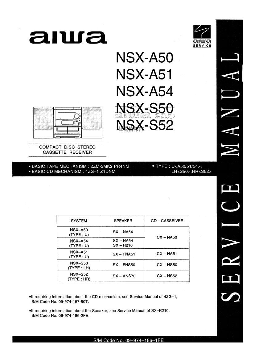
Aiwa NS XA54 Service Manual
This is the 46 pages manual for Aiwa NS XA54 Service Manual.
Read or download the pdf for free. If you want to contribute, please upload pdfs to audioservicemanuals.wetransfer.com.
Extracted text from Aiwa NS XA54 Service Manual (Ocr-read)
Page 2
, TABLE OF CONTENTS
SPECIFICATIONS ................................... ; ................................................................................ ....a 4
PROTECTION OF EYES FROM LASER BEAM DURING SERVICING
. PRECAUTION T0 REPLACE OPTICAL BLOCK .....
ELECTRICAL MAIN PARTS LIST
TRANSISTOR ILLUSTRATION
BLOCK DIAGRAM ...................
WIRING - 1 (MAIN :A50U,A54U) ..
SCHEMATIC DIAGRAM-1 (MAIN:A50U,A54U).
SCHEMATIO DIAGRAM -2 (MAIN : A51 U)
WIRING-2 (MAIN2A51U) ..
WIRING - 3 (MAIN: LH)...
SOHEMATIC DIAGRAM -3 (MAIN :LH).
SCHEMATIC DIAGRAM-4 (MAIN : HR).
WIRING-4 (MAIN : HR) ...........................
WIRING- 5 (FRONT : A50U,A54U) ............................
SCHEMATIC DIAGRAM- 5 (FRONT : A50U,A54U).
SCHEMATIC DIAGRAM - s (FRONT : A51U,LH,HR)
WIRING - e (FRONT 5 A51 U,LH,HR) ..........................
SCHEMATIC DIAGRAM - 7 (TUNER FRONT END) ..
WIRING-7 (AC) .....................................................
WIRING-8 (DECK) ...............................................
FL GRID ASSIGNMENT & ANODE CONNECTION.
IC BLOCK DIAGRAM-1
IC DESCRIPTION .............
IC BLOCK DIAGRAM-2.
ADJUSTMENT ...................
PRACTICAL SERVICE FIGURE.
MECHANICAL EXPLODED VIEW 1/1
MECHANICAL PARTS LIST 1/1 .....
ACCESSORIES / PACKAGE LIST ...................
TAPE MECHANISM EXPLODED VIEW 1/1
TAPE MECHANISM PARTS LIST 1/1 ,.
SPEAKER PARTS LIST ..............................
SPRING APPLICATION POSITION ..
REFERENCE NAME LIST .................
Page 20
WIRING-5 (FRONT: ASOU.A54U)
IIZISIIEIGI'II819|101n112l13lul
Page 36
6
10.
FM Tracking Check
Settings : ~ Test point : TP7, TPS
Method : - Set to PM 98.0MHz and check that the test point is
Z 1 6dB.
SW VT Adjustment (HR)
Settings : - Test point : TP3 (VT)
- Adjustment location : L942
Method : Set to SW 17.9MHz and adjust L942 so that the test
point becomes 7.0V 1 0.05V.
SW Tracking Adjustment (HR)
Settings : - Test point : TP7, TPS
° Adjustment location
5.9MHz
. l7.9MHz
Set up TC942 to center before adjustment.
The level at 5t9MHz is adjust to MAX by L941,
Then the level at 17.9MHz is adjust to MAX by
TC942.
Method :
DC Balance/ Mono Distortion Adjustment
Settings : 0 Test point : TP4, TPS
~ Adjustment location ; L771
- input level : 54dB
Method: Set to FM 98.0MHz and adjust L77] so that the
voltage between TP4 and TPS becomes 0V :9: 0.04V.
Next, check that the distortion is less than 1.3%
Auto Stop Level Check
Settings: ' Test point : TP6
- Input level : adjustable
Method : Set to FM 98.0 MHz and check that the voltage low
about 0. 1V. After that voltage high about 7.0V out
by ZdB down,
. Auto Stop Level Check
AM(MW)
Settings : . Input level : adjustable
Method : Set to AM(MW )lOOOkHz[A50U,A5] U,A54U,LH]
999kHz[HR] and check that the test point is 35 ~
60dB.
FM
Settings : - Input level : adjustable
Method : Set to PM 98,0MHZ and check that the test point is
25dB :l: lOdB,
SW (HR)
Settings: - lnput level : adjustable
Method : Set to FM lZMHz and check that the test point is
less than 60 dB.
< DECK SECTION >
12.
13.
14.
15.
17.
18.
_55_
Tape Speed Adjustment
Settings : - Test tape : 'ITA-lOO
~ Test point : TP2
- Adjustment location : SFRl
Method : Play back the test tape and adjust SFRl so that the
frequency counter reads 3000Hz : SHz.
Head Azimuth Adjustment
Settings : - Test tape : 'ITA-300
- Test point : TPZ
- Adjustment location : Head azimuth
adjustment screw
Play back the lOkHz signal of the test tape and adjust
screw so that the output becomes maximum.
Next, perform on each FWD PLAY and REV PLAY
mode.
Method :
PB Frequency Response Check (DECK l, DECK 2)
Settings: - Test tape : TIA-300
' Test point : TPZ
Play back the 315Hz and lOkHz signals of the test
tape and check that the output ratio of the lOkHz
signal with respect to that of the 315Hz signal is
within ZdB,
Method :
PB Sensitivity Adjustment (DECK l, DECK 2)
Settings : - Test tape : TEA-200
' Test point : TP2
- Adjustment location :
SFR301 (DECK 1, Lch)
SFR302 (DECK 1, R011)
SFR303 (DECK 2, Lch)
SFR304 (DECK 2, Rch)
Play back the test tape and adjust SFRs so that the
output level of the test point becomes
330mV[Deckl], 300 mV[Deck 2].
Method :
, REC/PB Frequency Response Adjustment
Settings : - Test tape : TIA-602
' Test point : TP2
- Input signal : lkHz/ lOkHz (LINE IN)
- Adjustment location: SFR35] (Lch)
SFR352 (Rch)
Apply a lkHz signal and REC mode.
Then adjust OSC attenuator so that the output level
at the TF2 becomes 210mV. Record and play
back the lkHz and lOkHz signals and adjust SFRs so
that the output of the lOkHz signals becomes OdB t
OlSdB with respect to that of the lkHz signal.
Method :
REC/PB Sensitivity Check
Settings: - Test tape : "PTA-602
. Test point : TPZ
' Input signal : lkHz (LINE IN)
Apply a lkHz signal and REC mode. Then adjust
OSC attenuator so that the output level at the TPZ
becomes ZlmVl Record and play back the lkHz
signals and check that the output is 17mV 1
3dB.
Method :
Bias OSC Frequency Adjustment
Settings: . Test point : TP9
- Adjustment location : L351
Method : Set to the REC mode. Adjust L351 so that the
frequency counter of the test point is ESkHz t lkHz.