Advent 300
This is the 17 pages manual for advent 300.
Read or download the pdf for free. If you want to contribute, please upload pdfs to audioservicemanuals.wetransfer.com.
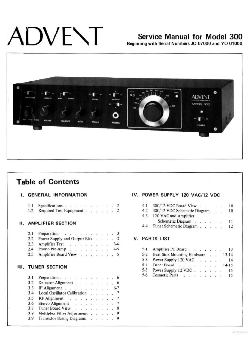
Extracted text from advent 300 (Ocr-read)
Page 1
I
A DV E\ I Service Manual for Model 300
Beginning with Serial Numbers J0 07000 and Y0 01000
ii MN
Table of Contents
I. GENERAL INFORMATION IV. POWER SUPPLY 120 VAC/12 VDC
l 1 Specifications , . 3 4.1 300/I2 VDC Board View . . . . . 10
1.2 Required Test Equipment . 2 42 300/12 VDC Schematic Diagram. . . 10
4.3 120 VAC and Amplifier
Schematic Diagram . . . . l
' AMPLIFIER SECTION 4.4 Tuner Schematic Diagram . . . . . ll
2.] Preparation . . . . . . 3
2.2 Power Supply and Output Bias . . . . 3 V. PARTS LIST
2.3 Amplifier Test . . . . . . . . 3-4
2.4 Phono Pre-Amp . . . . . . . . 4-5 51 AmplifichC Board . . . . . . l3
2.5 Amplifier Board View . , . . . , . 5 5-2 Heat Sink Mounting Hardware . . l3 l4
5-3 Power Supply 110 VAC . . . . . 14
5-4 Tuner Board . . . . . . 14-15
I . R ECTION
II TUNE S 5~5 Power Supply 12 VDC. . . . . . 15
3.1 Preparation. _ 6 5-6 Cosmetic Parts . . . . . . . . l5
3.2 Detector Alignment . . . . . . b
3.3 IF Alignment . , . . . . . 6-7
3.4 Local Oscillator ( alihratinn 7
3.5 RF Alignment 7
3.6 Stereo Alignment 7
3.7 Tuner Board View . . 8
3.8 Multiplex Filler Adjustment . 9
3.9 Transistor Basing Diagrams 9
Page 2
GENERAL INFORMATION
1.1 SPECIFICATIONS
Amplifier section
Continuous power output, both channels driven, 8 ohms
40 Hz to 20 kHz: 15 watts + 15 watts
1 kHz: 18 watts + 18 watts
Total harmonic distortion, 40 Hz to 20 kHz
15 watts.per channel: less than 0.5%
7.5 watts per channel: less than 0.1%
Intermodulation distortion
60/7000 Hz; 4: I: less than 0.15%
Preamp section
Maximum output: greater than 6V
Hum and noise, shorted input, A-welghted
Phone ref 10 mV @ 1 kHz: better than 80 dB
Aux, Tape monitor: better than 80 dB
Total Harmonic distortion
20 Hz to 20 kHz: less than 0.1% (2.5V)
lntermodulation distortion
60/7000 Hz; 4: 1: less than 0.1%(2.5V)
Tone controls
Bass: ilOdB @100 Hz
Treble: £10 dB @ 10,000 Hz
Infrasonic filter
Phono: 0 dB @ 25 Hz
-1 dB @ 20 Hz
-31 dB @ 4 Hz
FM tuner section
Mono sensitivity
ll-lF 30 dB: 2.5 uV'
IHF 50 dB: 3.5 uV
Stereo sensitivity
IHF 50 dB: 35 uV
Total harmonic distortion, 400 Hz, 1le
Mono: less than 0.15%
Stereo: less than 0.2%
Stereo separation, l]~lF
400 Hz: greater than 40 dB
30 Hz to 10 kHz: 28 (18
Alternate channel selectivity: 70 dB
Image rejection: 55 dB
IF rejection: 70 dB
Spurious rejection: 70 dB
AM suppression: 60 dB
Capture ratio: 1.6 dB
Antenna input: 300 ohms balanced
Power requirements
Model 300: 120 VAC, 60 Hz,
100 watts maximum
Model 300/12: 12 VDC, negative
ground, 7 amps maximum
1.2
REQUIRED TEST EQUIPMENT
The following list of test equipment is required to properly service the Model 300 stereo receiver.
1. Audio Oscillator, Hewlett Packard 204C or equivalent.
. Precision ACVM, Hewlett Packard 400 CL or equivalent.
. Oscilloscope, Tektronix T922 or equivalent.
Osmth
Sound Technology Model 1000A or equivalent.
\l
8. AC line varlac. General Radio W5MT3A or equivalent.
. Volt, Ohm Meter, Hewlett Packard Model 427A or equivalent.
. DistortioWHhr/lett Packard Model 333A or equivalent.
. FM Multiplex Generator, less than 0.2 TI-[D and better than -60 dB signal to noise.
. Two (2), Eight ohm load resistors, 1%, 25 watt minimum rating.
9. Frequency counter, 100 MHz, Data Precision Model 5740 or equivalent.